
Method and apparatus for improved single cell adaption due to change in environment

a technology of environment change and transmission method, applied in the direction of receiving monitoring, transmission monitoring, wireless commuication services, etc., can solve the problems of experienced channel conditions deviating further from initial assumptions, communication in the cell will not work very well, and the ability of the cellular communication system to improve. the effect of the ability

Active Publication Date: 2011-08-30
TELEFON AB LM ERICSSON (PUBL)
View PDF8 Cites 2 Cited by
  • Summary
  • Abstract
  • Description
  • Claims
  • Application Information

AI Technical Summary

Benefits of technology

This approach enhances system flexibility and efficiency by optimizing system parameters and selectivity according to current conditions, improving communication quality and reducing overhead, while avoiding degradation from excessive selectivity or channel estimation errors.

Problems solved by technology

Either the communication in the cell will not work very well, or the communication will be unnecessarily complex.
Variations in user behaviour over time can also cause the experienced channel conditions to deviate further from initial assumptions, for example, during busy hour.
A mobile unit moving through this standing wave pattern will experience rapid signal variations, fading, that present a challenge to upholding and optimizing the transmission and reception of information.
Movement of the receiving antenna through the standing wave pattern will result in signal variations in time.
Furthermore, even if both transmitter and receiver are stationary, movement and changes in the surroundings of the two may result in changes to the standing wave pattern and hence time variations of the received signal.
The time and frequency selectivity of the wireless communication channel presents a challenge to upholding efficient communication.
However, all of the described methods also have limitations depending on the time and frequency selectivity of the channel.
When the channel variations with time or frequency are slow compared to the extent of the transmitted data block the methods cannot provide resilience towards channel variations or C / I variations.
On the other hand, when the channel variations are very fast a large amount of overhead information is needed for the receiver to be able to estimate the channel, leaving less room for the transfer of information.
Frequency selectivity also introduces inter-symbol interference (ISI), which may lead to a need for channel equalization.
This will require more complex and costly receivers.
The drawback of this solution is added complexity and cost, and often the need for more overhead signalling.
If the frequency selectivity is increased too much increased inter-symbol interference and system degradation will result.
The additional time selectivity introduced in this way is beneficial in slowly varying channels but can cause problems if the channel is already varying rapidly.
On the other hand, if the channel for a certain user already provides sufficient selectivity, there is no additional gain from artificially creating more selectivity in the time or frequency domain.
It may even be harmful if the selectivity exceeds that required for the system to operate in an optimal way.
In this case time and frequency variations may be so rapid that they cause degradation due to, for example, inter-symbol interference or channel estimation errors.
For some users the performance would benefit from artificial selectivity while others might be harmed by it.
Selecting the appropriate amount of artificial selectivity becomes a difficult design choice that may have undesired consequences if the experienced channel conditions differ from the expected.
Yet another problem with the existing solutions is that both instantaneous and average channel characteristics will differ between the uplink and the downlink, as the artificial selectivity is only induced in one of the links.
Therefore, methods that rely on the similarity of the characteristics between uplink and downlink will suffer from degraded performance.
Artificially inducing a fixed amount of selectivity may limit the benefit of this flexibility, for example, if one user requires a large part of the available frequency band.

Method used


Image

  • Method and apparatus for improved single cell adaption due to change in environment
  • Method and apparatus for improved single cell adaption due to change in environment
  • Method and apparatus for improved single cell adaption due to change in environment

Examples


Embodiment Construction

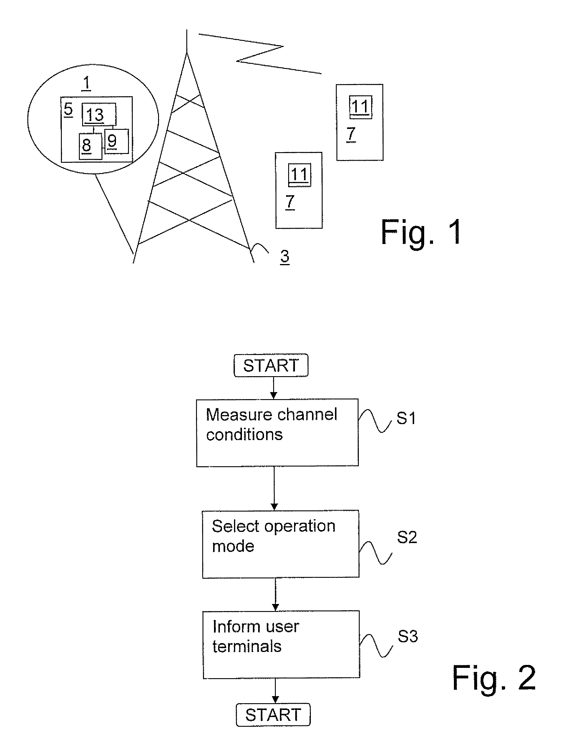
[0079]FIG. 1 shows a cellular telecommunications network 1 in which the principles of the present invention may be applied. A base station 3 is associated with, or comprises a control unit 5. The base station 3 communicates with one or more user terminals 7 in the cell through a wireless interface. The communication is affected by the layout and size of the cell, whether or not the terminals 7 are moving, and how fast, any reflecting objects that may be present in the cell, and possibly other factors. The skilled person is familiar with the factors affecting the communication in a cellular network.

[0080]The communication between the base station and the user terminals is bidirectional. Thus, both the base station 3 and the user terminals 7 comprise transmitters, receivers and control means for controlling the communication The control unit comprises a control means 8 for performing the control functions. Also, both the control unit 5 and the user terminals 7 preferably comprise moni...


PUM


Abstract

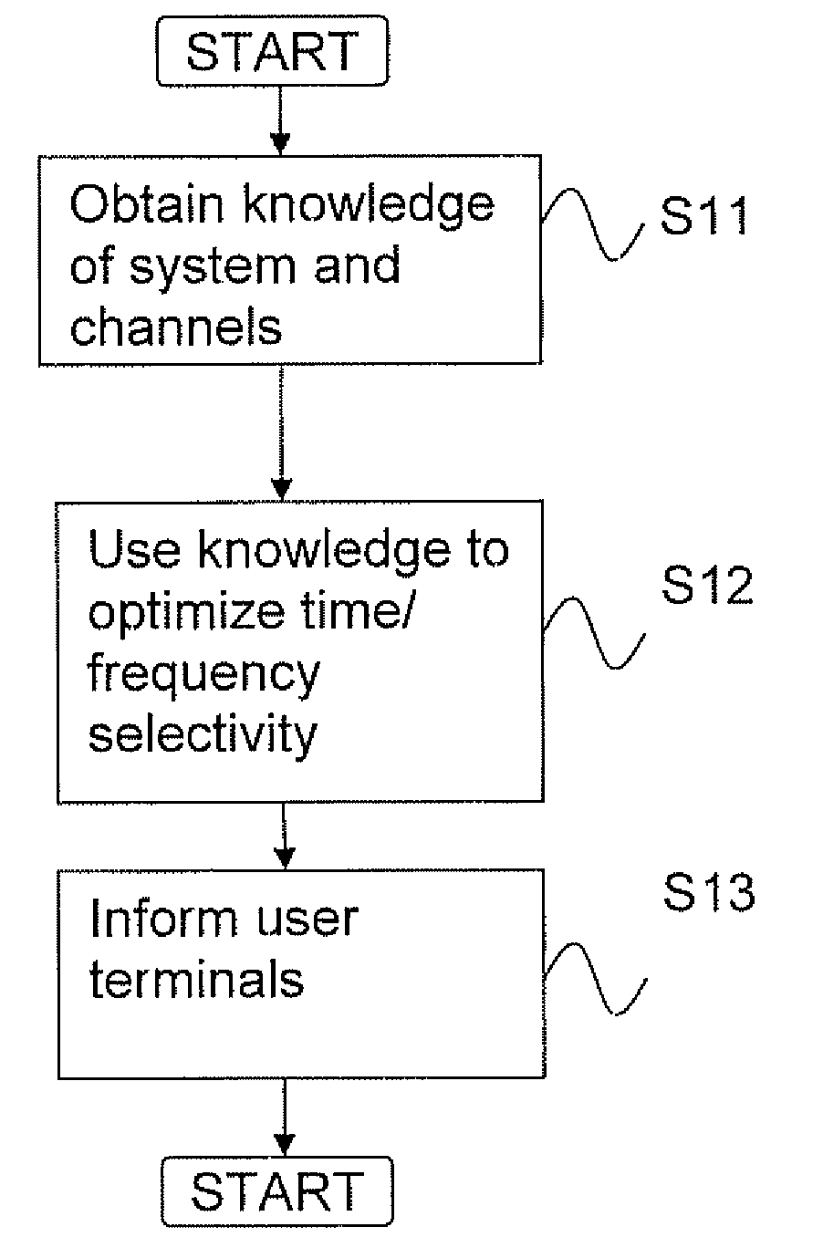
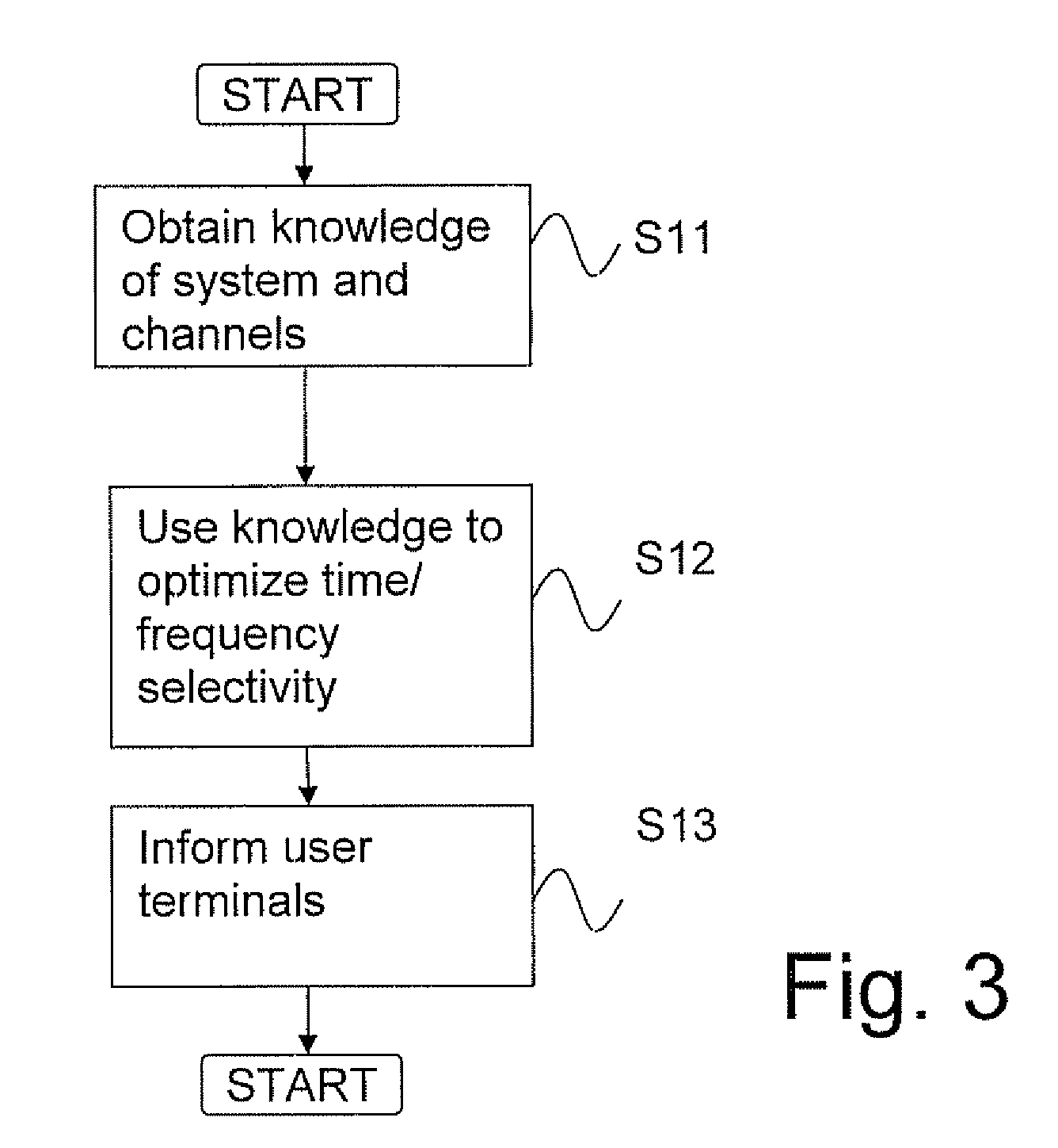
A communication method for use in a wireless communications network is proposed, said method comprising the steps of—monitoring at least one property representative of the channel variability in time and / or frequency, for each of at least two channels in the cell, used to communicate with said at least two user terminals; —using the result of the monitoring to control, by a control node in the network or in one of the user terminals, the communication in the cell. The control of the communication may include artificially inducing time selectivity and / or frequency selectivity or selecting an operating mode for the cell.

Description

TECHNICAL FIELD[0001]The present invention relates to a method and an apparatus for transmitting in a cellular communications network and in particular to the control of communication in such a network.BACKGROUND AND PRIOR ART[0002]In a typical cellular communications system there are many system parameters that should be adapted to the actual situation, and to each other, in order to make the system work as efficiently as possible. For example, certain physical layer parameters may be adapted, such as frame structure, pilot distribution and multiple antenna transmission mode (beamforming, MIMO, space-time coding and others).[0003]In a future system it may also be possible to select among different radio interfaces in a base station depending on the deployment scenario. For example, in micro or pico cells WLAN may be used and in large macro cells WCDMA or GSM / EDGE may be used.[0004]When adapting the system parameters the operator will try to match these to situations that may occur ...

Claims


Application Information

Patent Timeline
Patent Type & Authority Patents(United States)
IPC IPC(8): H04W4/00H04B1/02
CPCH04B17/24H04B17/382H04B17/373H04B17/309H04B7/04
Inventor ASPLUND, HENRIKRIBACK, MATHIASGORANSSON, BO
Owner TELEFON AB LM ERICSSON (PUBL)
Learn More