Infrared endoscopic balloon probes
a balloon probe and infrared technology, applied in the field of probes, can solve the problems of increasing the risk of complications for patients, limited ability of conventional endoscopes, and inability to detect all pathology or provide unequivocal, and devices that do not combine balloon endoscopes with infrared radiation to detect diseased tissu
- Summary
- Abstract
- Description
- Claims
- Application Information
AI Technical Summary
Benefits of technology
Problems solved by technology
Method used
Image
Examples
second embodiment
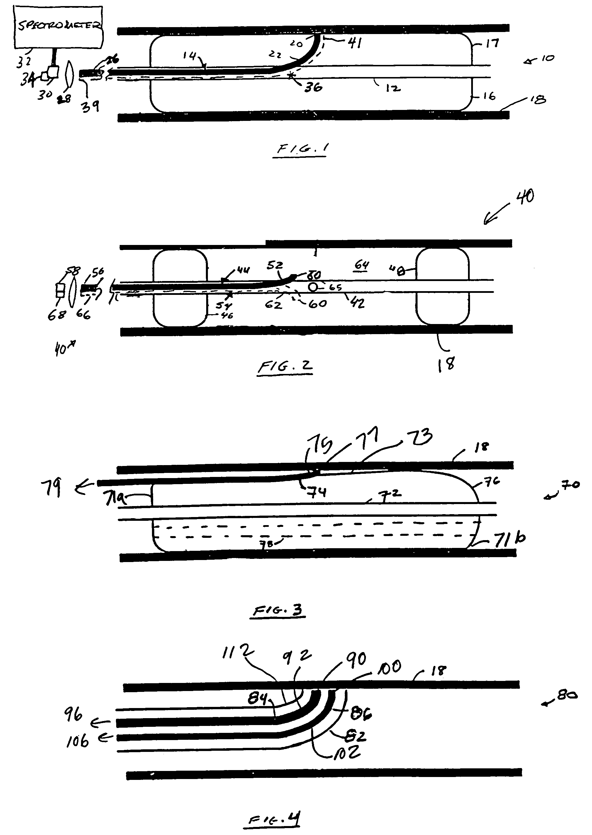
FIG. 2 depicts the present invention. Referring to FIG. 2, second probe device or probe 40 includes sheath 42, optical fiber 44, proximate balloon 46 and distal balloon 48. Optical fiber 44 includes distal optical collection end 50, proximal optical end 56, and bend 52 disposed proximate to collection end 50. Probe 40 may differ from probe 10 in that the collection end 50 is not in apposition with or disposed inside the balloon, but instead sits between the distal and proximate balloons. The collection ends of probe 40 may or may not be in apposition with tissue surface 18. Sheath or conduit 42 also includes opening 65 which connects or allows communication between the inside of sheath 42 with volume 64. Volume 64 is defined by proximate balloon 46, distal balloon 48, and tissue surface 18. Proximal optical end 56 of fiber 44 is functionally coupled to detector 58, such as a detector array, via a spectrometer.
first embodiment
Probe 40, like probe 10 of the first embodiment, may be implemented as a single-fiber or multi-fiber probe by providing one or more additional fibers 54 that run next to first fiber 44 in a bundle. Fibers 54 may each include a bend 62 in a different plane causing fibers 54 to diverge radially from first fiber 44 and from each other. Alternately, the fibers may have axially offset bends 62 in the same plane. Each of the fibers 54 has a distal collecting end 60 and a proximate end 66, which may be coupled to an additional detector 68 via a spectrometer. The first detector 58 and the additional detector(s) 68 may form part of a detector array, such as a focal plane array (FPA). Alternately, the multiple fibers in this embodiment may be serviced by a single detector and an optical multiplexer.
In operation, probe 40 is positioned in the area of interest, and distal and proximate balloons 46 and 48 are inflated. This creates cavity or enclosed volume 64 between the two balloons 46 and 48 ...
third embodiment
FIG. 3 depicts the present invention. Referring to FIG. 3, probe or probe device 70 includes sheath72, balloon 76 and fiber 74. Fiber 74 has a distal collection end 77 and a proximal end 79. In this embodiment, the fiber or fibers may be, but need not be, fixed to an outer surface 73 of balloon 76. Probe 70 may further include a bend 75, or a reflector that redirects light from collection end 77 into the fiber 74. The fiber or fibers may be introduced separately from the balloon using a guidewire. Apposition to the wall may be accomplished by simple inflation of balloon 76.
Although probes 10, 40 and 70 are occlusive, probes 10 and 70 may employ an autoperfusion balloon to allow antegrade blood flow during inflation. The balloon may be toroidally shaped. The balloon may have a passage 78 that is either centrally located or offset from the center. For example, as depicted in FIG. 3, passage 78 allows fluid communication between proximate end 71a and distal end 71b of balloon 70. Probe...
PUM
 Abstract
Description
Claims
Application Information
 - R&D
- Intellectual Property
- Life Sciences
- Materials
- Tech Scout
- Unparalleled Data Quality
- Higher Quality Content
- 60% Fewer Hallucinations
Browse by: Latest US Patents, China's latest patents, Technical Efficacy Thesaurus, Application Domain, Technology Topic, Popular Technical Reports.
© 2025 PatSnap. All rights reserved.Legal|Privacy policy|Modern Slavery Act Transparency Statement|Sitemap|About US| Contact US: help@patsnap.com


