Optical compensation film, polarizing plate and liquid crystal display device

a liquid crystal display device and optical compensation technology, applied in the direction of polarising elements, thin material processing, instruments, etc., can solve the problem of hardly achieving objects, and achieve the effect of superior image, superior phase difference, and excellent wavelength dispersion

Active Publication Date: 2011-09-27
FUJIFILM CORP
View PDF16 Cites 1 Cited by
  • Summary
  • Abstract
  • Description
  • Claims
  • Application Information

AI Technical Summary

Benefits of technology

[0023]It is an object of the present invention to provide an optical compensation film that allows superior phase difference between a first optically anisotropic layer and a second optically anisotropic layer and excellent wavelength dispersibility in terms of front and inclined retardation of liquid crystal layers in liquid crystal cells; it is another object of the present invention to provide a polarizing plate; it is still another object of the present invention to provide a liquid-crystal display device that can display superior images with less color change due to the polarizing plate.
[0072]In accordance with the third embodiment of the present invention, an optical compensation film can be produced with higher productivity, lower cost and less luminescent spots or defects without compensating optical properties.

Problems solved by technology

However, it is believed that these proposals could hardly attain the objects described above, since there is no description of techniques with respect to improvement of storage stability that is an essential or inherent problem in relation to polymerizable liquid crystal compounds.Patent Literature 1: Japanese Patent (JP-B) No. 3342417Patent Literature 2: Japanese Patent Application Laid-Open (JP-A) No. 08-50206Patent Literature 3: JP-A No. 07-333431Patent Literature 4: JP-B No. 2692035Patent Literature 5: JP-A No. 2005-122155Patent Literature 6: JP-A No. 2005-122156Non-Patent Literature 1: J. Applied Physics (1976) 47, p.

Method used


Image

  • Optical compensation film, polarizing plate and liquid crystal display device
  • Optical compensation film, polarizing plate and liquid crystal display device
  • Optical compensation film, polarizing plate and liquid crystal display device

Examples


first embodiment

Optical Compensation Film

[0082]In the first embodiment, the optical compensation film is one that comprises a first optically anisotropic layer and a second optically anisotropic layer.

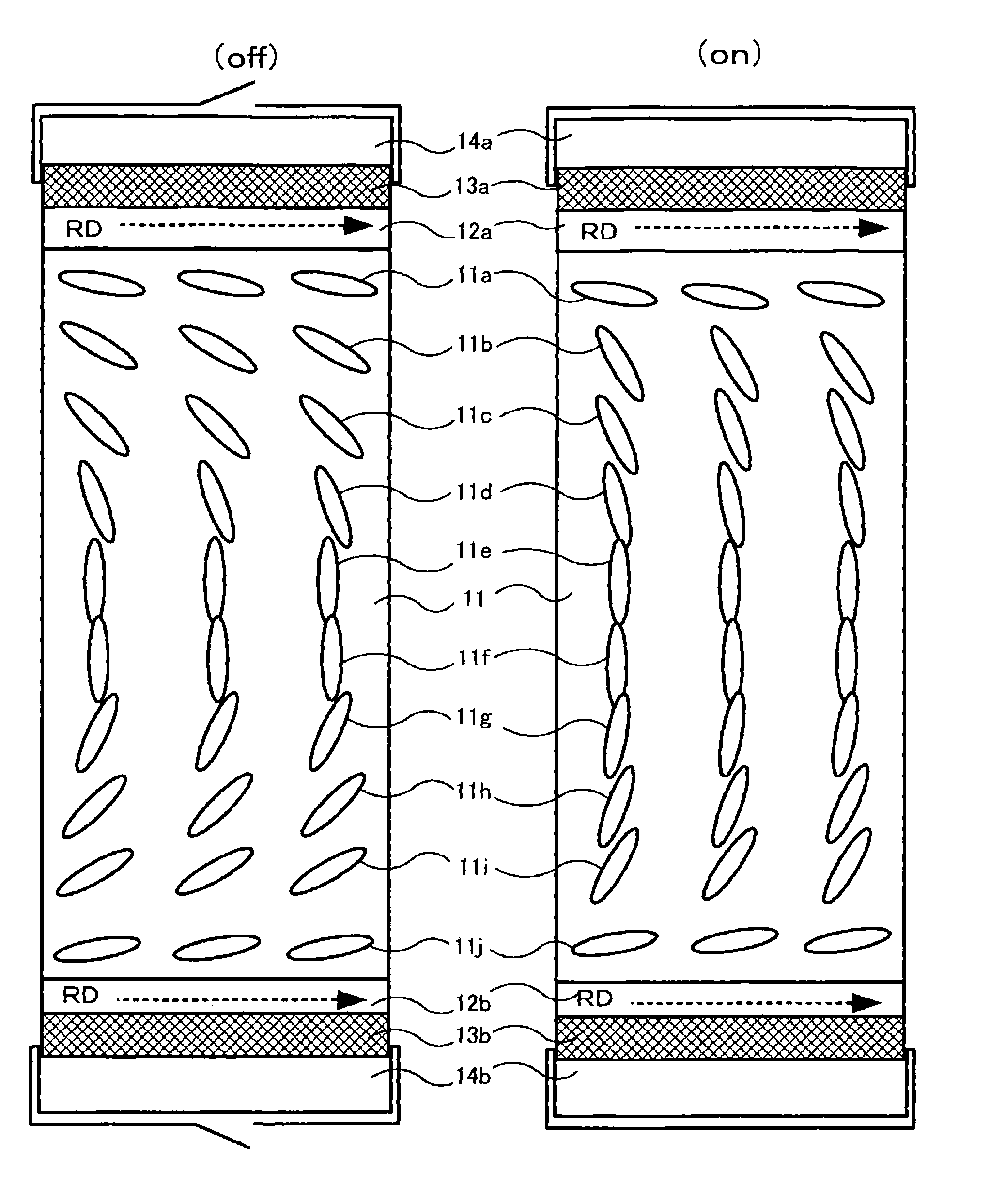
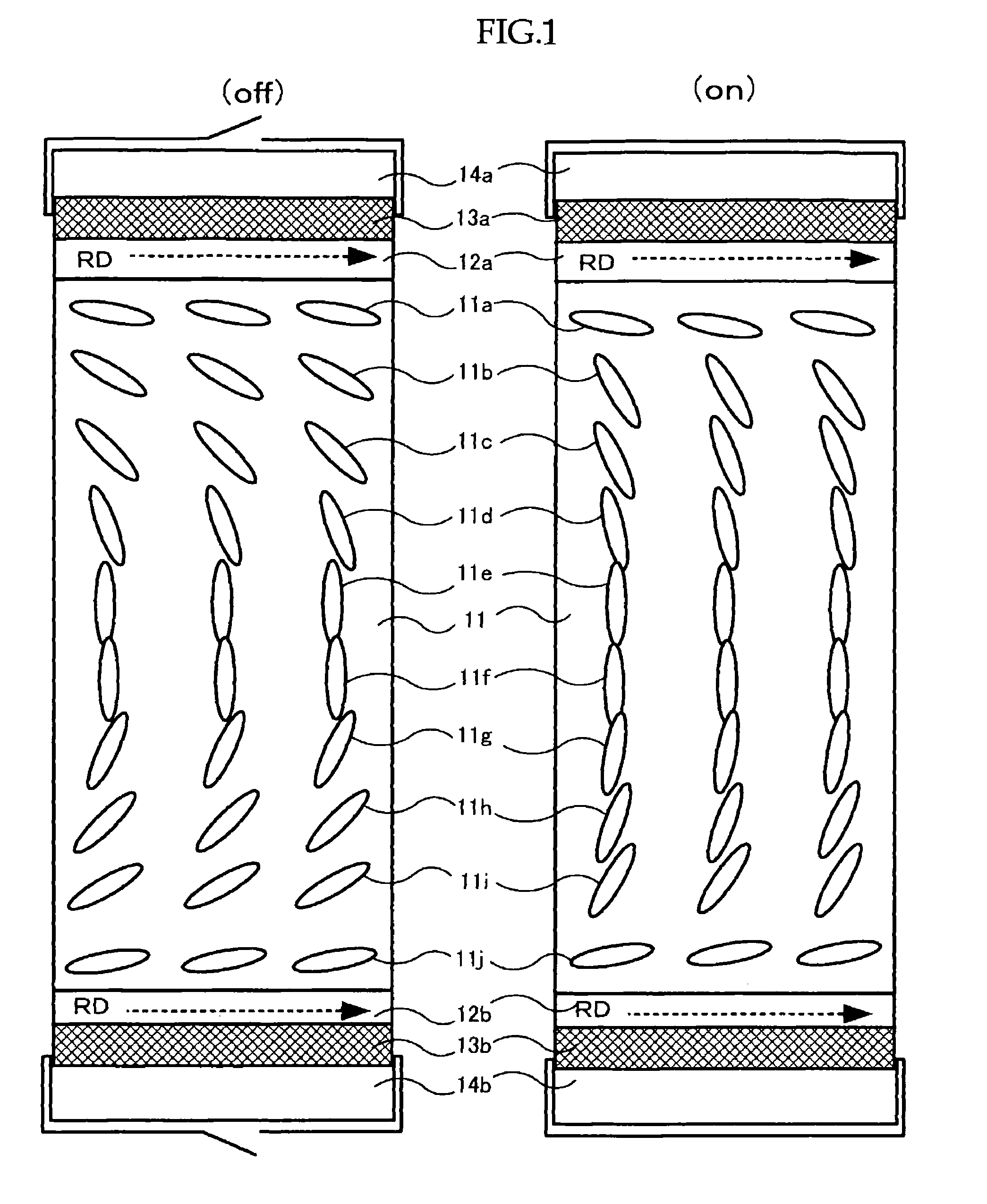
[0083]The optical compensation film has a function to solve such a problem of view-angle dependence through compensating phase difference of liquid crystal layers at near substrate interface that transmissivity or brightness changes depending on average orientation of liquid crystal molecules inclined at near substrate interface of liquid crystal devices, briefly speaking, the transmissivity or brightness changes when the view angle changes. The view-angle dependence can be improved, substantially perfect black display can be taken, and front contrast ratio can be increased by way of disposing the inventive optical compensation film at interface with substrates of the liquid crystal display devices.

[0084]In the inventive optical compensation film, the view-angle dependence can be improved by both opti...

second embodiment

Optical Compensation Film

[0389]The optical compensation films of the second embodiment comprise an orientation film and an optically anisotropic layer containing a liquid-crystal compound.

[0390]The optical compensation films comprise at least two layers of, for example, a cellulose acylate film and an optically anisotropic layer having an in-plane anisotropy, preferably further comprise an orientation film to control the orientation of liquid-crystal compounds between the cellulose acylate film and the optically anisotropic layer. The cellulose film and the optically anisotropic layer may be of two or more sheets respectively. The “cellulose acylate film” encompasses cellulose acetate films.

[0391]The difference Δγsd between γsd(AL) and γsd(LC) is no less than −4.0 erg / cm2, wherein γsd(AL) is a dispersion force component of surface free energy of orientation film (AL), γsd(LC) is a dispersion force component of surface free energy of liquid-crystal compound (LC), and Δγsd is calculat...

third embodiment

Optical Compensation Film

[0459]The optical compensation films of the third embodiment have an optically anisotropic layer formed by polymerizing and curing a composition, in which the composition comprises at least a liquid crystal compound, and the ratio of GPC pattern area, in a range of above 5000 of molecular weight in GPC chart after maintaining at 60° C. and 60% of relative humidity for three days, to entire GPC pattern area is no more than 0.1% (polystyrene conversion).

[0460]The GPC chart means the chart in which GPC is measured by the conditions and apparatuses described in GPC measurement method described below.

[0461]GPC pattern area in a range of above 5000 of molecular weight means the area that is represented as having molecular weights of no less than 5000 in polystyrene conversion from elution period and detected strength of elution pattern; the entire GPC pattern area means the area of entire elution pattern on GPC chart.

GPC Measuring Process

[0462](i) A sample is weig...


PUM

PropertyMeasurementUnit
inclination angleaaaaaaaaaa
surface free energyaaaaaaaaaa
liquid crystal temperatureaaaaaaaaaa

Abstract

The present invention aims to provide an optical compensation film that allows superior phase difference between a first optically anisotropic layer and a second optically anisotropic layer and excellent wavelength dispersibility in terms of front and inclined retardation of liquid crystal layers in liquid crystal cells, a polarizing plate containing the optical compensation film, and a liquid-crystal display device that can display superior images with less color change due to the polarizing plate.In order to attain the object, an optical compensation film etc. is provided that comprises at least a first optically anisotropic layer and a second optically anisotropic layer, wherein the first optically anisotropic layer satisfies at least one of the following Equations (i) to (iii):1≦Re1450)(0°) / Re1650)(0°)≦1.25:  Equation (i)1≦Re1450)(40°) / Re1650)(40°)≦1.25:  Equation (ii)1≦Re1450)(−40°) / Re1650)(−40°)≦1.25:  Equation (iii).

Description

TECHNICAL FIELD[0001]The present invention relates to optical compensation films, and polarizing plates and liquid crystal display devices that utilize the optical compensation films.BACKGROUND ART[0002]Liquid crystal display devices are typically equipped with liquid crystal cells and polarizing plates. The polarizing plates, typically formed of a protective film and a polarizing film, are produced by dying a polarizing film of polyvinyl alcohol films by use of iodine and stretching the film, then laminating the protective film to the both sides. In liquid crystal display devices of transmission-type, in some cases, the polarizing plates are attached to both sides of liquid crystal cells and also one or more optical compensation films are disposed. Liquid crystal display devices of reflection-type are typically formed from a reflective plate, a liquid crystal cell, one or more of optical compensation films, and a polarizing plate in this order.[0003]The liquid crystal cells are typ...

Claims


Application Information

Patent Timeline
Patent Type & Authority Patents(United States)
IPC IPC(8): G02B5/30C09K19/52G02F1/13363
CPCG02B5/3083G02F1/133632G02F1/1393Y10T428/10Y10T428/1041Y10T428/1059G02F2413/105C09K2323/031C09K2323/05C09K2323/00
Inventor MATSUBARA, RYOTATAKAHASHI, YUTAIKEDA, AKIRAYOSHIKAWA, MASARUHOSOKAWA, TAKAFUMINAGAI, MICHIOTAKAHASHI, MAKOTO
Owner FUJIFILM CORP
Why Eureka
Try Eureka