Rotating anticathode X-ray generating apparatus and X-ray generating method

a technology of generating apparatus and rotating anticathode, which is applied in the direction of x-ray tube target and convertor, x-ray tube gas control, nuclear engineering, etc., can solve the problems of deteriorating utilization efficiency of rotating anticathode, and achieve the effect of suppressing the consumption of rotating anticathod

Inactive Publication Date: 2011-09-27
SAKABE NORIYOSHI +2
View PDF3 Cites 1 Cited by
  • Summary
  • Abstract
  • Description
  • Claims
  • Application Information

AI Technical Summary

Benefits of technology

It is an object of the present invention, in a rotating anticathode X-ray generating apparatus and an X-ray generating method, to suppress the consumption of the rotating anticathode by the irradiation of electron beams onto the rotating anticathode.
In a still further embodiment, the film includes at least one selected from the group consisting of graphite, diamond, alumina, calcium oxide, magnesium oxide, titanium oxide, titanium carbide, silicon, boron and boron nitride. Particularly, the film includes the graphite. Since the listed material can exhibit a smaller relative density and a smaller vapor pressure at high temperature, the listed material is preferable as the material of the film because the listed material is unlikely to be solid-solved with the material of the rotating anticathode such as Cu or Co and to vaporize by itself. If the film includes a material with electric conduction, the electric charge of the film due to the irradiation of the electron beam can be suppressed so that the destruction of the film can be prevented effectively and efficiently.

Problems solved by technology

However, since the electron beam irradiating portion is held on the cylindrical portion by the centrifugal force caused by the rotation of the rotating anticathode, the melted portion of the electron beam irradiating portion can not be splashed.
As a result, the rotating anticathode (cylindrical portion) is consumed remarkably so that the utilization efficiency of the rotating anticathode may be deteriorated.[Patent Application No. 1]Japanese Patent Application Laid-open No. 2004-172135

Method used


Image

  • Rotating anticathode X-ray generating apparatus and X-ray generating method
  • Rotating anticathode X-ray generating apparatus and X-ray generating method
  • Rotating anticathode X-ray generating apparatus and X-ray generating method

Examples


Embodiment Construction

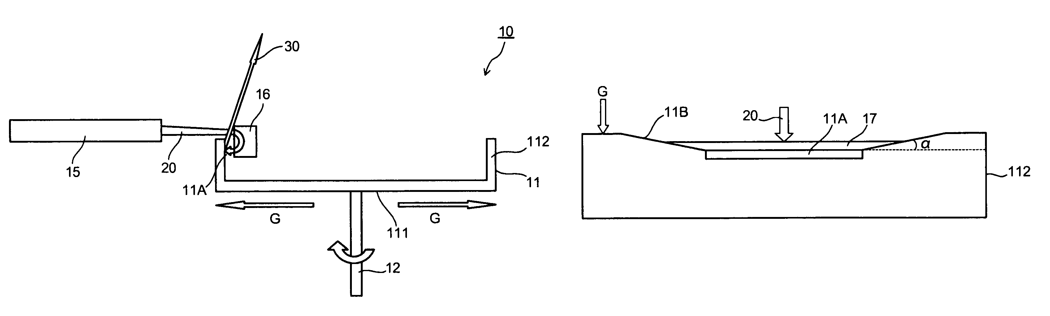
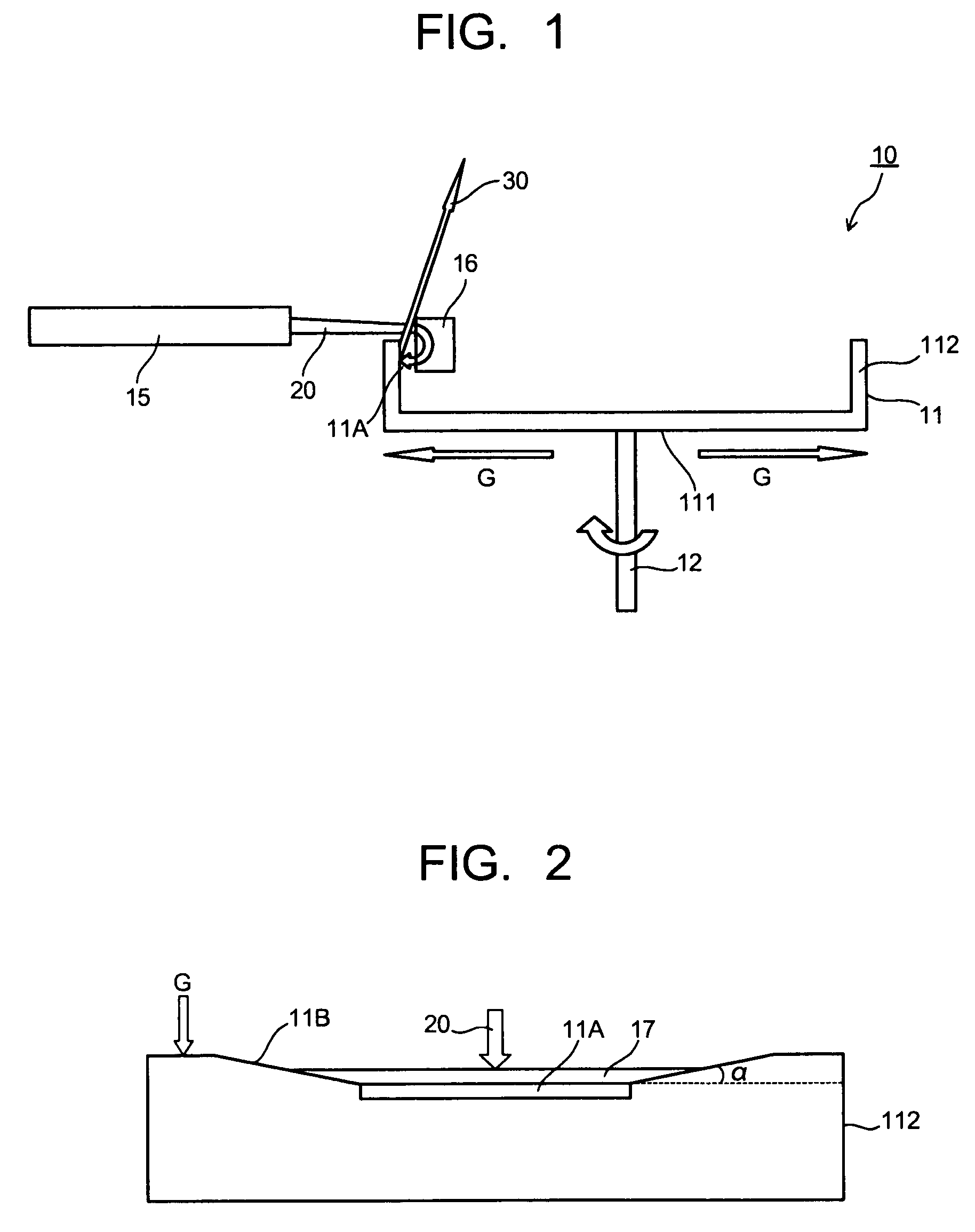
Hereinafter, the present invention will be described in detail with reference to the drawings. FIG. 1 is a structural view showing the essential part of a rotating anticathode X-ray generating apparatus according to the present invention. FIG. 2 is an enlarged view showing the area containing the electron beam irradiating portion in the rotating anticathode X-ray generating apparatus shown in FIG. 1.

As shown in FIG. 1, the rotating anticathode X-ray generating apparatus 10 includes an rotating anticathode 11 and an electron gun 15 as an electron beam source. The rotating anticathode 11 includes a main body 111 mechanically connected with a rotating shaft 12 and a cylindrical portion 112 provided vertically for the main body 111. The cylindrical portion 112 constitutes the side wall of the rotating anticathode 11. The main body 111 is formed almost circularly so that the cylindrical portion 112 is provided vertically at the periphery of the main body 111. The rotating anticathode 11 ...


PUM


Abstract

A rotating anticathode X-ray generating apparatus which is configured such that an X-ray is generated by an irradiation of an electron beam emitted from a cathode includes a rotating anticathode with an electron beam irradiating portion to generate the X-ray through the irradiation of the electron beam so that a direction of the electron beam is set equal to a direction of a centrifugal force caused by a rotation of the rotating anticathode; and a film for covering at least the electron beam irradiating portion so as to prevent an evaporation of a material making the rotating anticathode.

Description

CROSS-REFERENCE TO RELATED APPLICATIONSThis application is based upon and claims the benefit of priority from the prior Japanese Patent Application No. 2007-181979, filed on Jul. 11, 2007; the entire contents of which are incorporated herein by reference.BACKGROUND OF THE INVENTION1. Field of the InventionThis invention relates to a rotating anticathode X-ray generating apparatus and an X-ray generating method for generating an X-ray with ultrahigh brightness.2. Description of the Related ArtIn X-ray diffraction measurement, it may be required to irradiate an X-ray with as high intensity as possible onto a sample. In this case, a conventional rotating anticathode type X-ray generating apparatus would be employed for the X-ray diffraction measurement.The rotating anticathode X-ray generating apparatus is configured such that an electron beam is irradiated onto the outer surface of the columnar anticathode (target) in which a cooling medium is flowed while the anticathode is rotated a...

Claims


Application Information

Patent Timeline
Patent Type & Authority Patents(United States)
IPC IPC(8): H01J35/10
CPCH01J35/10H01J35/14H01J2235/086H01J2235/165H01J2235/18H01J2235/20
Inventor SAKABE, NORIYOSHI
Owner SAKABE NORIYOSHI
Why Eureka
Try Eureka