
Motor apparatus and method

a technology of motors and containers, applied in the direction of motor/generator/converter stoppers, electric controllers, dynamo-electric converter control, etc., can solve the problems of affecting the life of washing machines, affecting the wear of brakes, and high cost of using brake pads or shoes to stop washing machines tubs

Inactive Publication Date: 2011-10-11
GENERAL ELECTRIC CO
View PDF30 Cites 5 Cited by
  • Summary
  • Abstract
  • Description
  • Claims
  • Application Information

AI Technical Summary

Benefits of technology

[0083]Another advantage of the embodiments of the present invention is that additional hardware is avoided and braking can be performed during substantially all negative slip. Another advantage is that input voltage from a power outlet is not used to brake or stop the motor while performing an embodiment of the present invention. Also, the present invention provides a cost effective design since it dissipates energy of the washing machine motor by avoiding the use of prior art elements such as brake shoes or pads or brake resistors. Brake pads and brake resistors add to the unit cost of a washing machine.

Problems solved by technology

The use of brake pads or shoes to stop a washing machine tub is costly and also affects the life of the washing machine dependent upon use since each brake shoe or pad has a wear surface that is subject to wear and eventually, after a period of use, will fail due to wear.
A large load may spin longer and at greater angular velocity than a small load; thus causing greater wear on the brake.
A higher water level, using more water than a lower level, less full load, would also require additional spin for water removal and could cause greater wear on the brake.

Method used


Image

  • Motor apparatus and method
  • Motor apparatus and method
  • Motor apparatus and method

Examples


Embodiment Construction

Washing Machine Introduction

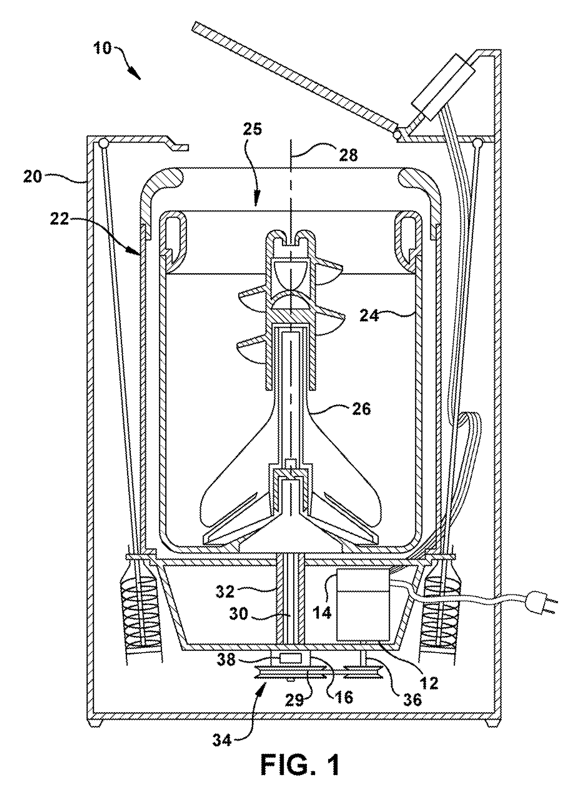
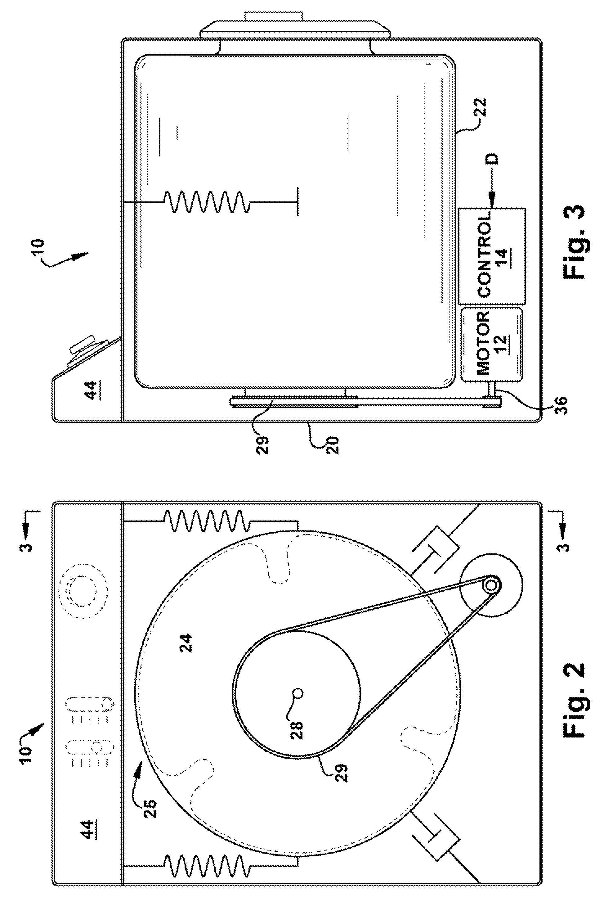
[0040]Referring to the drawings and in particular to FIG. 1, a washing machine (“washer”) according to an exemplary embodiment of the present invention is illustrated and is generally referred to by reference numeral 10. For purposes of clarity, aspects of washer 10 necessary for understanding of the present disclosure, as well as aspects helpful in understanding the operation of washer 10 are described herein. Washer 10 described herein can be a vertical axis washer 10 as is illustrated in FIG. 1 or a horizontal axis washer 10, as is illustrated in FIGS. 2 and 3. One of ordinary skill in the art can perform the exemplary embodiments of the invention described herein using either configuration. Like reference numerals are used in the horizontal and vertical axis washer illustrations.

[0041]Washer 10 includes a motor 12 and a motor control unit 14. Motor 12 is a three-phase alternating current (AC) induction motor and, in some embodiments includes motor con...


PUM


Abstract

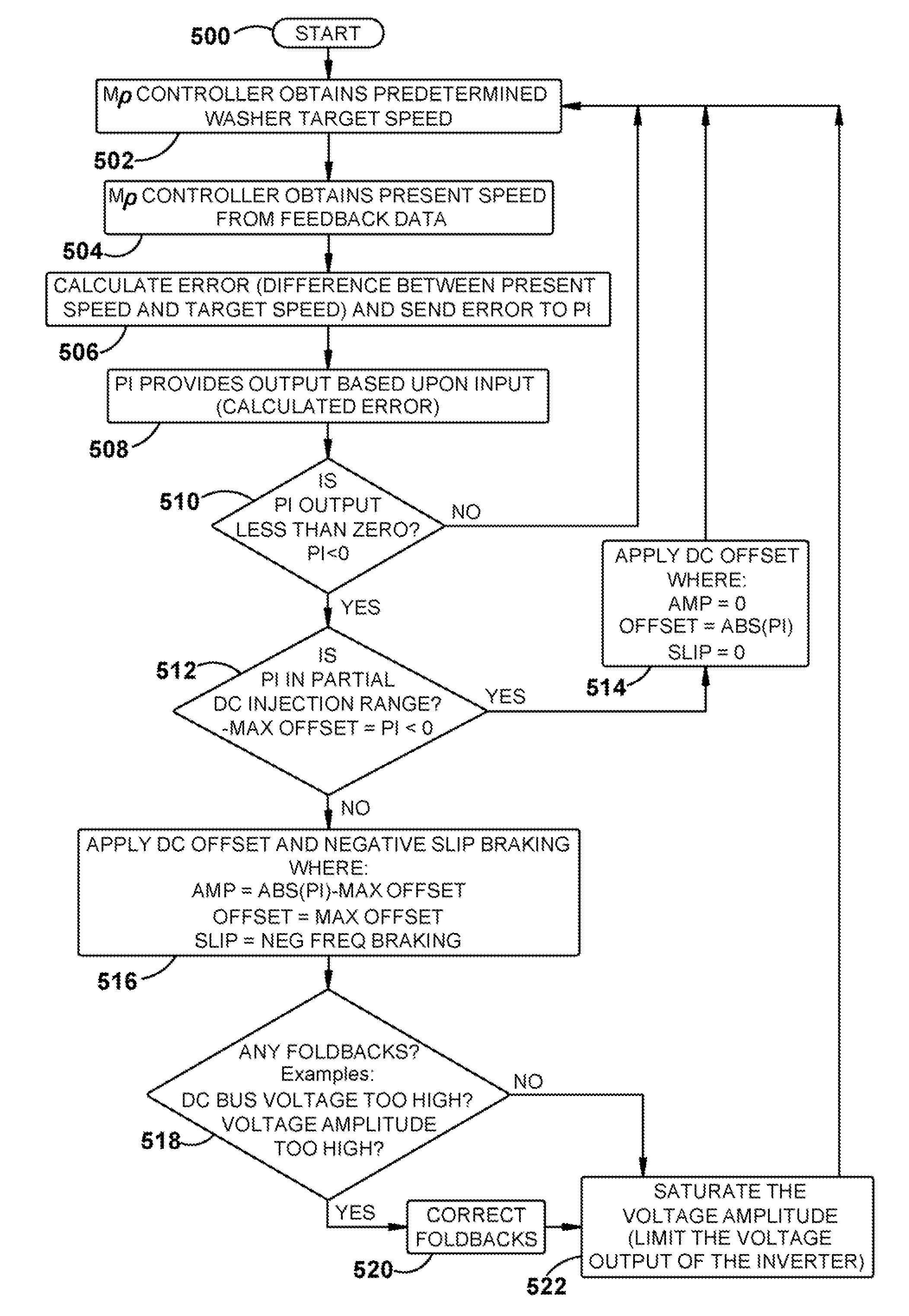
A method of operating a motor, the method comprising: operating a motor at a first speed; operating the motor in negative slip; imbalancing at least one phase of the motor to dissipate regeneration energy using windings of the motor; and wherein a next motor speed is decreased to a speed less than the first speed. An apparatus for carrying out the method is also presented.

Description

BACKGROUND OF THE INVENTION[0001]1. Field of the Invention[0002]The present disclosure is related to a rotating container. More particularly, the present disclosure is related to the braking of a tub or basket that is subject to a rotational speed.[0003]2. Description of Related Art[0004]Vertical axis washing machines, also known as top loading washing machines, represent a large portion of the overall washing machine consumer market in the United States. Horizontal axis washing machines represent a smaller segment of the United States market and abroad typically represent a larger portion of the overall washing machine consumer market.[0005]Most vertical axis and horizontal washing machines include a spin cycle for removing water and / or detergents from the laundry using centrifugal force and spinning a wash load tub, also referred to as a laundry tub (“tub”) or basket. During a typical spin cycle, the motor, typically an induction motor, of the washing machine spins the tub at rela...

Claims


Application Information

Patent Timeline
Patent Type & Authority Patents(United States)
IPC IPC(8): H02P3/18
CPCD06F33/02D06F37/304H02P3/18H02P3/24H02P23/0063H02P23/08D06F2202/065D06F2204/065H02P2207/01H02P23/20D06F2103/24D06F33/30D06F34/08D06F2105/46
Inventor FILIPPA, MARIANOHATFIELD, EDWARDSUEL, II, RICHARD D.HOLMES, JOHN STEVEN
Owner GENERAL ELECTRIC CO
Learn More