
Photocatalytic reactor and process for treating wastewater

a photocatalytic reactor and photocatalytic technology, applied in water/sludge/sewage treatment, water treatment parameter control, specific water treatment objectives, etc., can solve the problems of limited efficiency, complex operation and maintenance, and inefficient filtering, so as to facilitate its assembly and maintenance, facilitate the construction of the reactor, and facilitate the effect of transport and installation

Active Publication Date: 2011-10-18
UNIV CATOLICA DE LA SANTISIMA CONCEPCION
View PDF3 Cites 12 Cited by
  • Summary
  • Abstract
  • Description
  • Claims
  • Application Information

AI Technical Summary

Benefits of technology

The reactor achieves stable and continuous pollutant removal and disinfection without the need for previous fitting periods or thermophilic conditioning, operating effectively at low temperatures and allowing for the use of antibiotics, while maintaining efficiency in treating a portion of the total water volume.

Problems solved by technology

Nevertheless, its efficiency is limited by the presence of suspended solids, which causes a “shadow” or shield effect over bacteria and other microorganisms.
A good development has been achieved by these treatment systems, however, they exhibit some inconveniences, as the operation and maintenance complexity, and the non-efficient filtering, which maintains the hydrobiological species submitted to amonnium and carbon dioxide sub-lethal concentration levels.
Further, these systems require a minimal dissolve ammonia concentration in water, for avoiding the bacteria inactivation or death, and its filtration efficiency is affected by the existence of the competitiveness for the environmental conditions, of other bacteria degrading organic matter.
These facts can turn the biologic filter very unstable, requiring stabilization periods, which can be a risk for the continuity of the hydrobiological species production in the confined culture, causing lethal water quality levels.
Though, the ammonium degradation is increased, the economic viability (by the use of platinum) and the environmental viability (by the use of N2O, gas from the greenhouse effect) makes difficult its use in a massive way.

Method used


Image

  • Photocatalytic reactor and process for treating wastewater
  • Photocatalytic reactor and process for treating wastewater
  • Photocatalytic reactor and process for treating wastewater

Examples


examples

[0108]As an example, a laboratory assay was carried out for the ammonium removal process, using a real sample of water from a trout (Onchorynchus mykiss) culture, from the Centro de Cultivo Piloto de la Universidad Católica de la Santísima Concepción, Chile.

[0109]The water from the culture was filtered at 45 μm and then prepared for the treatment using photocatalysis and the radicals produced by ozone. The pH value was increased to 12 using NaOH and the process was begun. The following corresponds to the obtained result:

[0110]

AmmoniumTreatmentconcentrationNitriteBacterial loadTOCDQOtime (min)(mg / l)(mg / lt)(U.F.C.)(mg / lt)(mg / lt)02.41.210,3006560100401200.950025Replication02.31.11230060600.9700401200.90027

[0111]The assays show that in two hours, the ammonium removal was 58%. Total disinfection was achieved and the dissolved organic matter was reduced by more than 50%.


PUM


Abstract

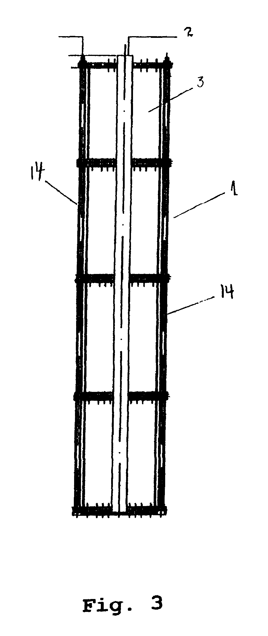
A photocatalytic reactor with a modular configuration, based on UV light sources and a catalyst, useful for purifying and disinfecting wastewater from confined aquaculture, using Advanced Oxidation Processes (AOP), wherein the catalyst is supported over glass sheets as fixed strips within the reactor, at an established distance from the UV light source, and wherein the wastewater is treated as “batches” being re-circulated and returned to the circuit. The wastewater is fed through the lower end of the reactor and submitted to a strong turbulence when passing through perforations or holes made on the supports forming the floors that separate the reaction chambers.

Description

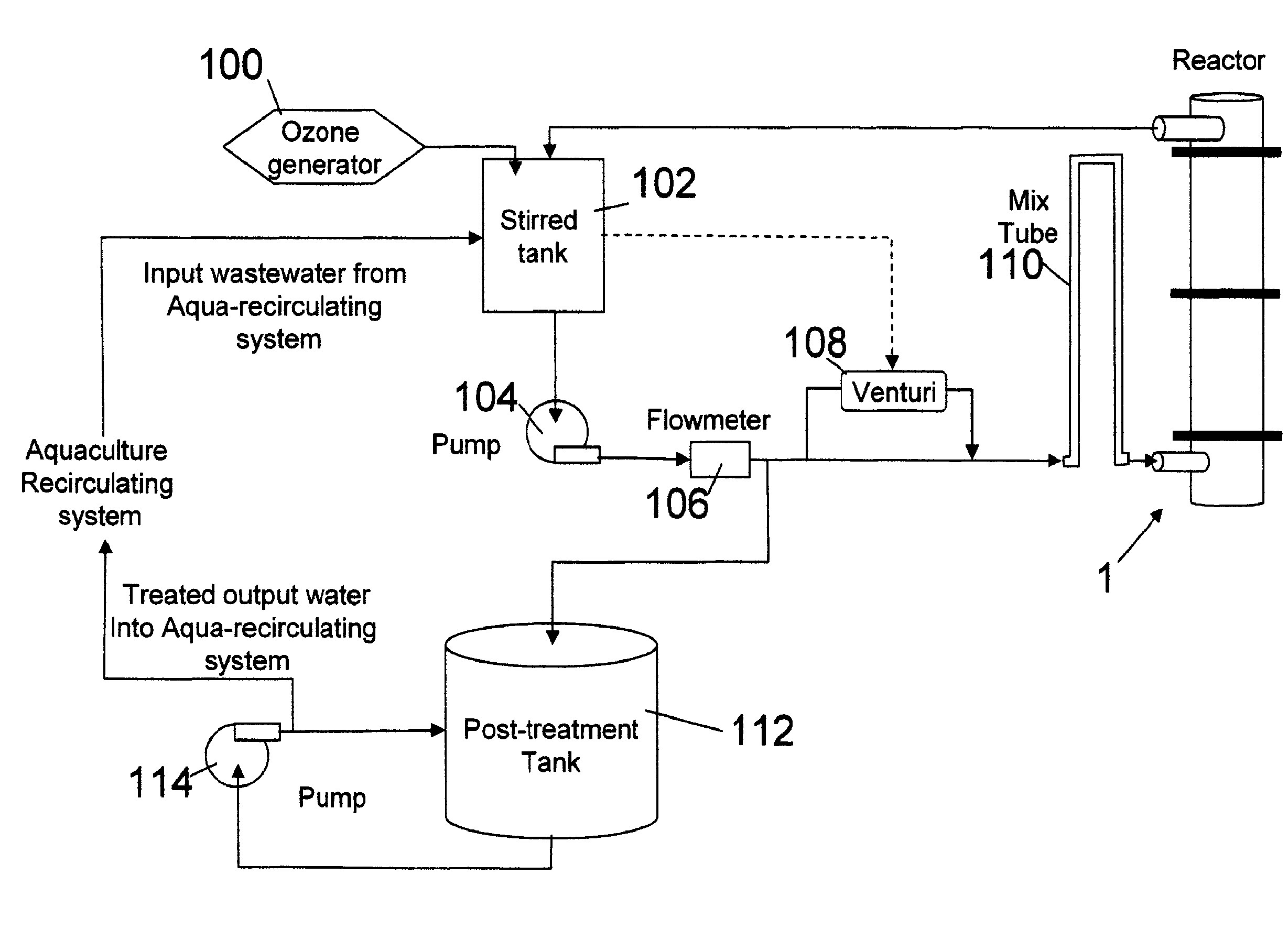
BACKGROUND OF THE INVENTION[0001]The present invention is related with a photocatalytic reactor based on UV light sources and a supported titanium dioxide (TiO2) based catalyst, and gas ozone for producing hydroxyl radicals, useful for purifying wastewater from confined aquaculture systems, mediated by an advanced oxidative process. The photocatalytic reactor uses a substrate comprising a supported catalyst, which allows the removal of ammonium, nitrite, as well as the removal of water soluble organic matter and water disinfection, it also refers to the method for using and the operation of the same.[0002]A variety of treatments or methods for purifying water, for removing nitrogenous compounds, and for removing the dissolved organic matter, specifically in waste water from the culturing of hydrobiologic species, are known in the prior art, said methods comply independently or in combination of their functions. Among the better known of said methods are composed of the biologic filt...

Claims


Application Information

Patent Timeline
Patent Type & Authority Patents(United States)
IPC IPC(8): B01J19/08
CPCC02F1/725C02F1/32Y02W10/37C02F2303/04C02F2209/06
Inventor CABELLO, PABLO ARTURO VENEGASORTIZ, MARIA CRISTINA YEBERDINAMARCA, ANA LORENA NARVAEZVENNEKOOL, CATTERINA DEL PILAR SOBENESSANHUEZA, CARLOS MAURICIO ORTIZMORALES, HECTOR VALDES
Owner UNIV CATOLICA DE LA SANTISIMA CONCEPCION
Learn More