Coated drill and method of making the same

a technology of coating drill and twist drill, which is applied in the direction of twist drill, superimposed coating process, manufacturing tools, etc., can solve the problems of affecting the life of reconditioned drills, pitting or pitting wear, and difficult to achieve the optimum properties of twist drill parts, etc., to achieve good chip transportation and good wear resistance

Active Publication Date: 2011-10-25
SANDVIK INTELLECTUAL PROPERTY AB
View PDF29 Cites 8 Cited by
  • Summary
  • Abstract
  • Description
  • Claims
  • Application Information

AI Technical Summary

Benefits of technology

[0010]An object of the present invention is to provide a twist drill with good wear resistance at the tip area and with good chip transportation properties in other parts of the twist drill.
[0012]Yet another object of the present invention is to provide a twist drill that is less prone to pitting formation.

Problems solved by technology

Hence, achieving optimum properties for different parts of a twist drill can be difficult and several attempts have been made to accomplish this.
Another problem, which especially applies to twist drills coated along the cylindrical land, is referred to as pitting or pitting wear and includes spalling of the wear resistant coating on the cylindrical land and typically in the area close to the drill corner.
However, when the drill is reconditioned it is often reduced somewhat in length and hence the worn region comes close to the cutting region and therefore the pitting can be detrimental to the life time of a reconditioned drill.
Unfortunately, such coatings are very strongly prone to such pitting formation.

Method used


Image

  • Coated drill and method of making the same
  • Coated drill and method of making the same

Examples


example 1

Invention

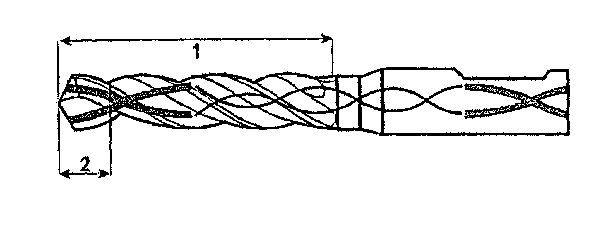
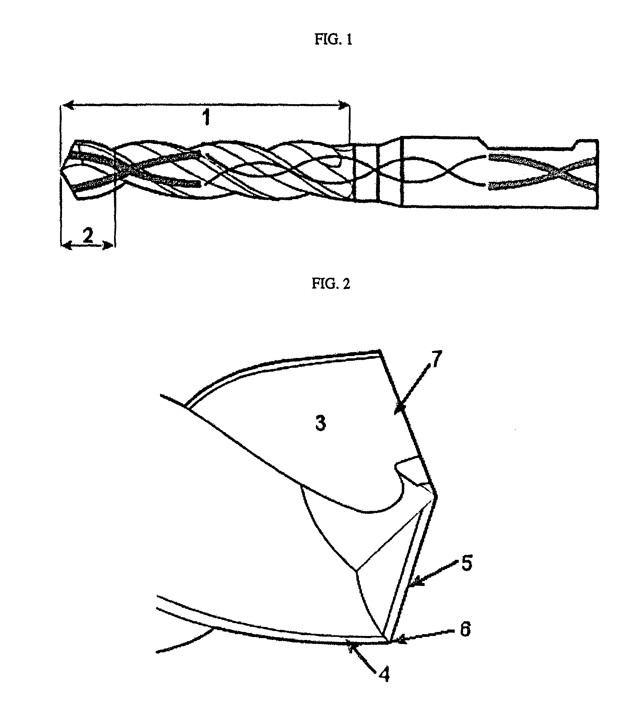
[0073]Coated 8 mm drills according to the present invention were made by depositing a first and a second layer system, both having aperiodic multilayer structures, using reactive PVD arc discharge evaporation onto cemented carbide drills with a composition of 10 wt-% Co and balance WC. The multilayer structures were deposited from two arc targets, 1 and 2, with the drills mounted on a 3-fold rotating substrate table arranged in order to obtain the aperiodic structure. The arc evaporation was performed in an Ar+N2-atmosphere. After depositing the first layer system, the drills were subjected to a wet blasting treatment. Before depositing the second layer system, a part of the drill was shielded by a cylinder so that only the tip area of the drill was coated with the second layer system. The tip area was the area from the tip and approximately 10 mm from the tip. The composition of the two arc targets and the average composition of the first and second layer system are shown ...

example 2

Reference

[0076]Coated 8 mm drills were made where the drills were either coated with only one layer system over the whole active part of the drill, or, coated with one layer system covering only the tip part of the drill. The layer systems both had aperiodic multilayer structures and were deposited using reactive PVD arc discharge evaporation onto cemented carbide drills with a composition of 10 wt-% Co and balance WC. The multilayer structures were deposited from two arc targets with the drills mounted on a 3-fold rotating substrate table arranged in order to obtain the aperiodic structure. The evaporation was performed in an Ar+N2 gas mixture.

[0077]The tip area was the area from the tip and about 10 mm from the tip. The compositions of the two arc targets and the average composition of the layer systems are shown in Table 2.

[0078]The multilayered structure had a sequence of individual layers with an aperiodic, i.e. non-repetitive thickness. Cross section transmission electron micr...

example 3

[0080]Drills made according to Example 1 were compared to Ref. 1 in Example 2. Two drills of each drill type were tested in a drilling operation during the following cutting conditions:

[0081]

Work piece material:Tool Steel, 42CrMo4Operation:DrillingVc m / min130Feed mm / rev0.30Vf mm / min1460t1 mm20Note:Wet conditions, emulsion 6%

[0082]The results can be seen below. The tool life travel is an average of two tests.

[0083]

TABLE 3Drill type No.Tool life travel (m)1 (Invention)55Ref. 131


PUM

PropertyMeasurementUnit
thicknessaaaaaaaaaa
diameteraaaaaaaaaa
diameteraaaaaaaaaa

Abstract

The present invention relates to a drill comprising a cemented carbide or high speed steel substrate and a coating wherein the coating comprises: a first layer system having a multilayered structure covering substantially the whole active part of the drill, a second layer system having a multilayered structure covering only the tip area of the drill.Drills according to the present invention have good wear resistance and improved properties when reconditioning the drill.The present invention also relates to a method of making a drill according to the present invention.

Description

BACKGROUND OF THE INVENTION[0001]The present invention relates to a twist drill for metal machining coated with a first and a second layer system, wherein the first layer system has been deposited over substantially the whole active part of the twist drill whereas the second layer system has been deposited only onto the tip area of the twist drill. The present invention also relates to a method of manufacturing such a twist drill.[0002]Twist drills are often coated with a hard material to increase tool life by enhancing the wear resistance. A high wear resistance is advantageous at the tip area of the twist drill where the cutting takes place whereas properties like low friction and smoothness are advantageous on other parts of the twist drill, for example, to enhance chip transportation. The chip transport is particularly important when the drilled depth is relatively large compared to the nominal diameter. In some cases, by coating the chip flutes, the chip transport can, compared...

Claims


Application Information

Patent Timeline
Patent Type & Authority Patents(United States)
IPC IPC(8): B23B51/02
CPCB23B51/02C23C30/005C23C28/044C23C28/42B23P15/32B23B2224/24B23B2224/28B23B2224/32B23B2224/36B23B2228/10Y10T29/49986Y10T408/9097Y10T408/78Y10T407/27C23C14/06C23C14/16
Inventor ANG.STRAND, MARIAMULLER, PETERSCHNEIDER, THOMASHEIL, THOMAS
Owner SANDVIK INTELLECTUAL PROPERTY AB
Why Eureka
Try Eureka