
Polymer delivery in well treatment applications

a well treatment and polymer technology, applied in the direction of transportation and packaging, well accessories, sealing/packing, etc., can solve the problems of high equipment and energy costs of this process, slow process for hydration of polymers in oilfield applications, and still not as fast as desired, so as to limit the solubility of a rheological agent, easy to pump, and low viscosity

Inactive Publication Date: 2011-10-25
SCHLUMBERGER TECH CORP
View PDF16 Cites 25 Cited by
  • Summary
  • Abstract
  • Description
  • Claims
  • Application Information

AI Technical Summary

Benefits of technology

[0013]In an embodiment, the present invention uses a partitioning agent that severely limits the solubility of a rheological agent, such as a polymer. As a result, the mixture forms a water-in-water emulsion where a concentrated rheological agent is concentrated in the dispersed phase, as a viscous aqueous solution or as water-wet, hydrated, or partially hydrated particles, and the partitioning agent is concentrated in the continuous phase. One exemplary, non-limiting system comprises guar as the viscosifying agent and polyethylene glycol (PEG) as the portioning agent. Guar is commonly used to viscosify treatment fluids at relatively low concentrations, e.g. 0.1 weight percent, and at higher concentrations in water the fluid can become too thick to pump or pour. The water-in-water emulsion of concentrated guar in embodiments of the present invention has a relatively low viscosity and is very easily pumped, but when diluted with water at the wellsite, the binodal point is crossed and a continuous aqueous polymer phase forms to readily viscosify the fluid.
[0014]The concentrated guar embodiment thus has a low viscosity convenient for transport to the wellsite and / or preparation of the well treatment fluid, but thickens rapidly when diluted in the treatment fluid. Moreover, and unexpectedly, partitioning agents such as the PEG embodiment can be used effectively in the water-in-water emulsions at concentrations relative to the viscosifying polymer that, upon dilution in the well treatment fluid, are sufficiently low to minimize any deleterious effects on the treatment fluid in terms of, for example, rheology, stability, crosslinkability, and so on.
[0015]Another benefit of the water-in-water emulsion is that the mixture is easily flowable or pumpable, even though a comparable mixture of the water and polymer alone without any partitioning agent would be very thick or paste-like. This allows the water-in-water emulsion to be made at high polymer content and at the same time the polymer particles are contacted with the aqueous medium and at lest partially water swollen, while at the same time dispersed in the aqueous partitioning agent solution. The swollen guar or other polymer in the water-in-water emulsion thus has a head start on the hydration process and can thus be hydrated in water or aqueous fluid more quickly relative to dry guar.
[0016]More importantly, the swollen guar in the water-in-water emulsion can be further processed in beneficial ways to additionally enhance rapid hydration. For example, mechanical processing such as wet grinding of the water-in-water emulsion can be used to break the guar particles into smaller pieces and thus achieve faster hydration, but without the problems noted above in the prior art dry grinding. The swollen guar particle is relatively larger and softer than the dry counterpart, which facilitates the grinding. In wet grinding, the heat generated can be dissipated in the liquid medium. Since the grinding is also cushioned by the fluid, there is less reduction of the polymer molecular weight. Furthermore, the progressively smaller particles formed during the wet grinding are already dispersed in water, and are not susceptible to form fish-eyes. Preheating the concentrated guar mixture can now be an efficient way to promote hydration since it is not necessary to heat the entire liquid phase of the well treatment fluid and the concentrate represents only a small fraction of the total fluid.
[0017]In one embodiment, the invention provides a method of treating a subterranean formation penetrated by a well bore. The method can include the steps of: (1) mixing a rheological polymer, a partitioning agent and a first liquid medium to form a heterogeneous mixture comprising a dispersed rheological polymer-rich phase and a partitioning agent-rich phase; (2) diluting the heterogeneous mixture with a second liquid medium miscible with the first liquid medium to mutually dissolve the polymer-rich phase and the partitioning-agent rich phase and form a well treatment fluid comprising a continuous mixed polymer-agent phase; and (3) injecting the well treatment fluid into the well bore. In embodiments, the rheological polymer can be a thickening polymer effective to increase the viscosity of the well treatment fluid; or a friction reducer effective to reduce friction pressure losses when the well treatment fluid is pumped in the well bore at a high flow rate, e.g. 4 m / s.
[0035]A further embodiment of the invention provides a method for supplying a hydrated polymer solution. The method can include the steps of: (a) supplying rheological polymer solids, a partitioning agent and a first aqueous stream to a mixing zone to form a water-in-water emulsion stream; (b) optionally mechanically, thermally or mechanically and thermally processing the water-in-water emulsion stream to improve hydratability of the rheological polymer; and (c) supplying the water-in-water emulsion stream with a second aqueous stream to a dilution zone to form a rheologically modified aqueous stream.

Problems solved by technology

Hydration of polymers for oilfield applications is generally a slow process.
Although the process and hydration time has been shortened through multiple efforts in the past decades, it is still not as quick as desired, i.e. reaching above 80% final fluid viscosity in less than 1 or 1.5 minutes.
The equipment and energy costs of this process are high.
However, there have been several issues associated with the use of very small guar particles.
Grinding the dry guar polymer can have a detrimental effect on the polymer performance because the grinding process can physically break the molecular chains and thus lower the polymer molecular weight and therefore lower the ultimate gel viscosity yield.
In addition, the smaller the particle size, the harder it is to grind in terms of grinder geometry, energy input, heat dissipation control, and so on, which in turn lead to higher costs.
Thus, the knowledge that finer particles will potentially shorten hydration time has not led to effective improvements to reduce the time to complete the hydration process.
These batch treatment processes had numerous limitations since gel once made could decompose from bacteria, and any gel not used at the wellsite was wasted.
Additionally, batch mixing did not readily allow for changes in gel concentrations or loading during the course of a treatment.
Non-aqueous slurries comprise dry polymer suspended in an oil solvent, often diesel fuel which presents some difficulties.
To minimize the use of oil suspensions, service companies have also developed dry systems in which dry polymer is directly mixed with water, but such systems can present another set of difficulties known to those of skill in the art.
Similar difficulties are encountered when adding a friction reducer such as acrylamide homopolymer or copolymer to low viscosity fracturing fluids known as slickwater fluids, which typically contain only 0.025 to 0.2 weight percent of the friction reducer, in addition to other conventional additives such as biocides, scale inhibitors, clay stabilizers such as potassium chloride, trimethylammonium chloride or the like.
To reduce turbulent flow in the slickwater fluid, the friction reducer must “flip” from the emulsion to rapidly dissolve in the water, usually within several seconds, or else the full drag reduction will not be achieved during transit through the wellbore.
Also, dilution of the friction reducer in a brine solution has been used to collapse ionic polymer chains and reduce the viscosity of the concentrated friction reducer solution; however, storage stability has been an issue because any contact with fresh water, such as condensate dripping inside a storage tank, immediately forms fisheyes, which cannot be redispersed.
Although numerous continuous mix systems are now in the oilfield, none is completely satisfactory, and considerable need remains for systems with improved hydration properties.

Method used


Image

  • Polymer delivery in well treatment applications
  • Polymer delivery in well treatment applications
  • Polymer delivery in well treatment applications

Examples


example 1

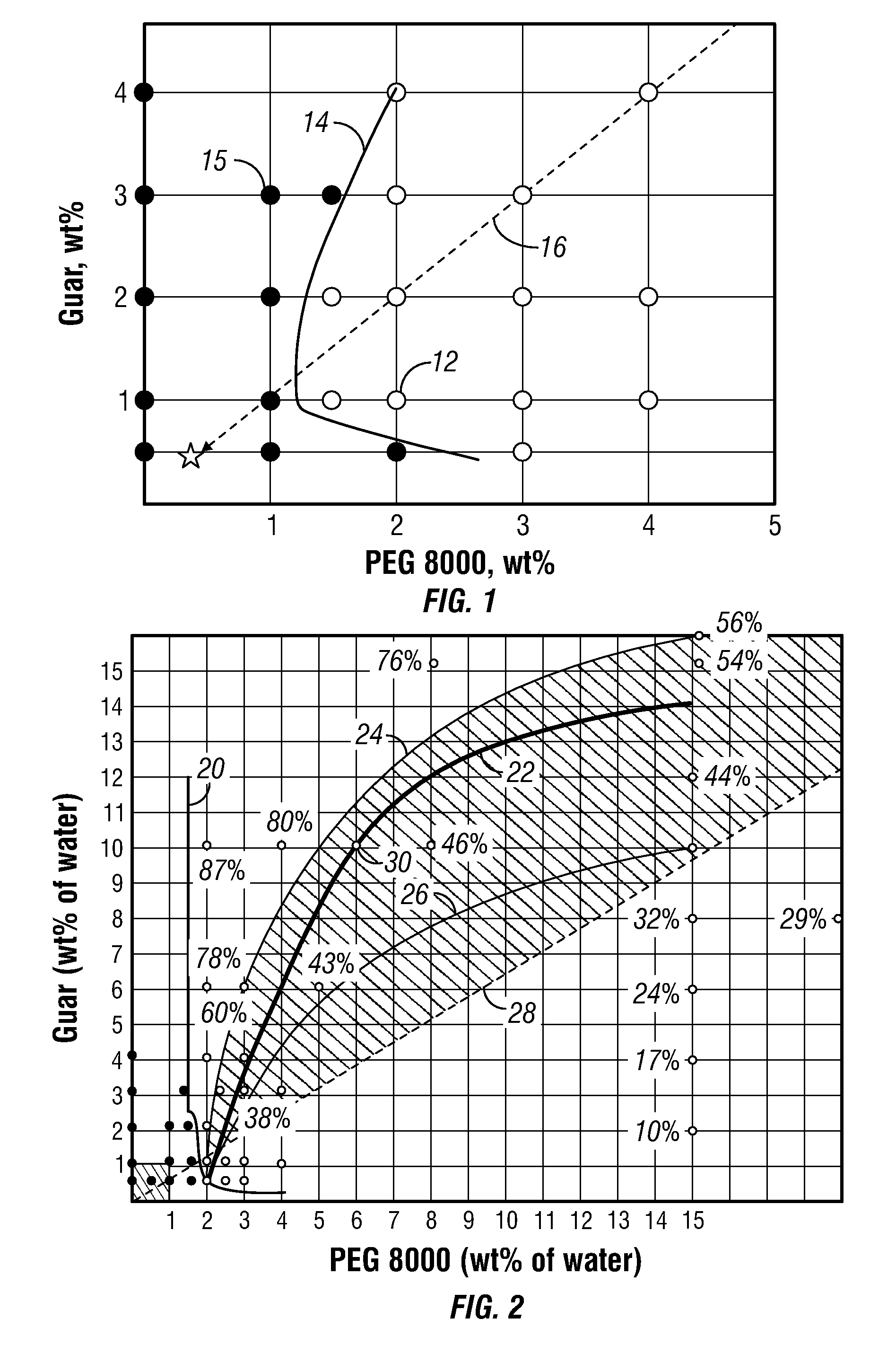
[0088]A low viscosity aqueous suspension of guar with PEG 8000. A series of polymer solutions was created by dissolving 0-4 weight percent dry guar and 0-4 weight percent dry polyethylene glycol (PEG 8000) in deionized (DI) water. In each case, 200 ml of DI water were used, and the polymers were measured as dry powders with percentages expressed on a total fluid weight basis. For each sample, the dry polymers were mixed together and then added together into the DI water while stirring vigorously in a WARING blender. Each sample was stirred rapidly in the blender for a minimum of one hour. After this stirring process, each sample was visually inspected for evidence of phase separation. Samples were monitored for a period of at least 24 hours to check for phase separation. The results were plotted in FIG. 1 using filled circles 10 to indicate no phase separation and open circles 12 to indicate the occurrence of phase separation.

[0089]The low-viscosity concentrates 12 fell within the t...

example 2

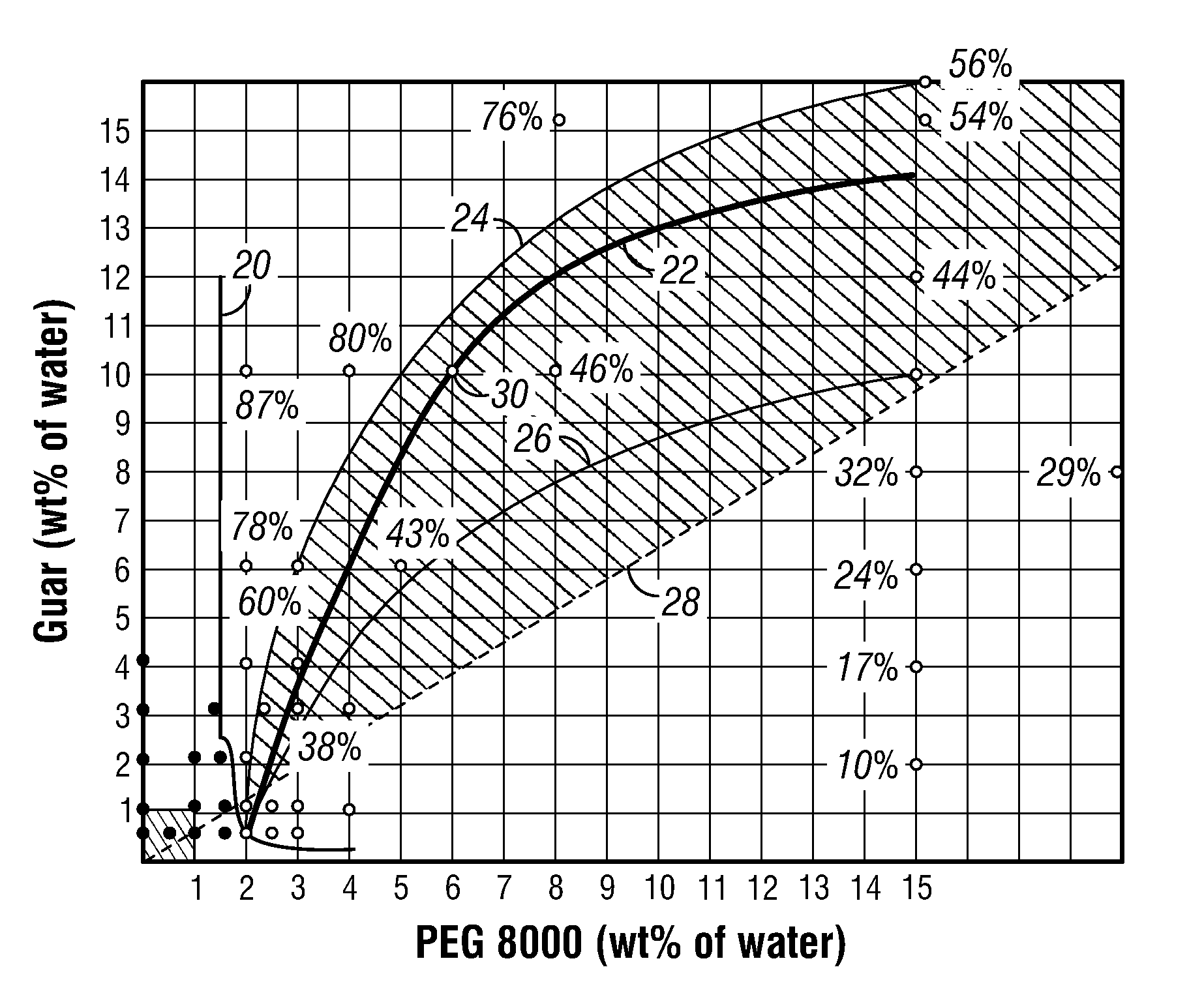
[0092]Wellsite guar delivery system using low viscosity aqueous suspension. FIG. 2 provides a phase diagram for a high molecular weight guar routinely used for wellbore treatment fluids. As in the phase diagram of FIG. 1, the guar in this example was again phase separated with PEG 8000. Line 20 on the phase diagram indicates the binodal for phase separation, with compositions to the upper-right of line 20 being low viscosity two-phase solutions of the two polymers in water. Line 22 in the two-phase region indicates the line of compositions having 50 / 50 phase volume upon phase separation; line 24 a 60 / 40 phase volume of guar:PEG 8000; and line 26 a 40 / 60 phase volume of guar:PEG 8000. The percentages beside some of the points are the volume percent of the separated guar phase at equilibrium. Below-right with respect to the line 24 (60 / 40 guar:PEG 8000) represents readily pourable compositions; compositions above 60 to about 80 volume percent guar phase are borderline pumpable, genera...

example 3

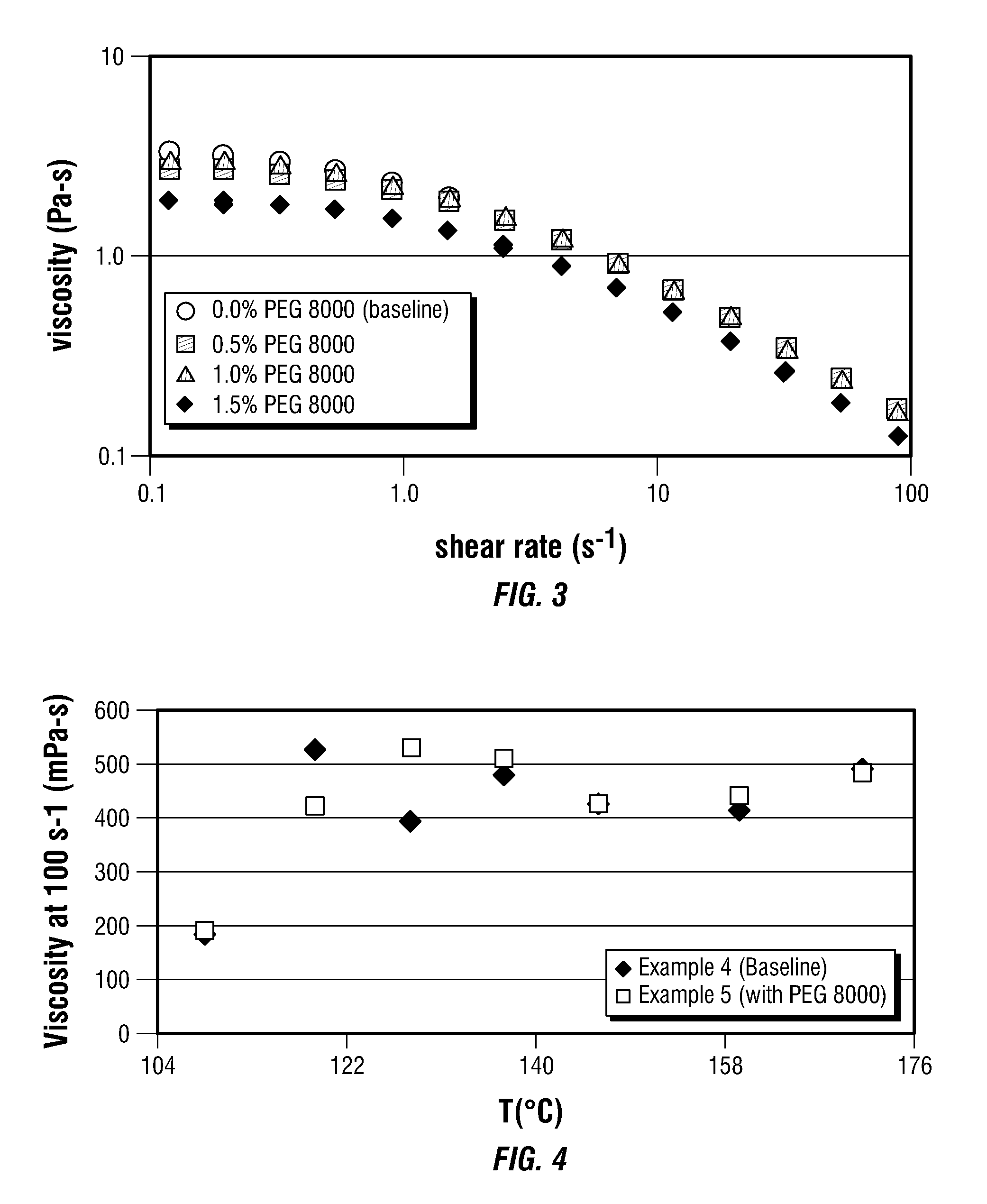
[0095]Effect of diluted PEG 8000 on viscosity of linear gels. FIG. 3 shows the rheology of 0.5 wt % guar solutions with and without addition of PEG 8000, in terms of apparent viscosity versus shear rate. Concentrations of PEG 8000 less than approximately 1 wt % do not measurably alter the rheology of 0.5 wt % guar solutions. Specifically, the data shown in FIG. 3 illustrate that addition of PEG 8000 to a 0.5% guar solution (40 lbs / 1000 gallons) has negligible impact on the guar solution rheology for PEG 8000 concentrations up to at least 1 wt %. This is a critical, unexpected result, that a phase-separated, low viscosity concentrate can be used to deliver guar as a treatment fluid, without sacrificing the performance of the guar fluid thus made when the dilution is performed to create a final fluid composition within the area 32 from zero to 1% for both guar and PEG concentration in FIG. 2.


PUM

PropertyMeasurementUnit
temperatureaaaaaaaaaa
volume percentaaaaaaaaaa

Abstract

This invention relates to compositions and methods for treating subterranean formations, in particular, oilfield stimulation compositions and methods using water-in-water polymer emulsions to uniformly dissolve a rheologically active polymer, such as a thickener or friction reducer, in the treatment fluid. The emulsions have a low viscosity and are easily pumped for mixing into a treatment fluid, where upon dilution with an aqueous medium, the polymer is easily hydrated without forming fish-eyes. The partitioning agent in the water-in-water emulsion does not generally affect the rheology of the treatment fluid. The invention also relates to further processing of the emulsion by wet grinding, high shear mixing and / or heating to enhance the hydration rate in the preparation of the well treatment fluid.

Description

CROSS REFERENCE TO RELATED APPLICATIONS[0001]This application claims priority to and the benefit of U.S. 60 / 959,836, filed Jul. 17, 2007 and U.S. 61 / 054,277, filed May 19, 2008.BACKGROUND OF THE INVENTION[0002]This invention relates to methods for and fluids used in treating a subterranean formation. In particular, the invention relates to the preparation and use of polymer delivery systems in the form of concentrated polymer suspensions useful for creating wellbore fluids and in methods of treating subterranean formations.[0003]Various types of fluids are used in operations related to the development and completion of wells that penetrate subterranean formations, and to the production of gaseous and liquid hydrocarbons from natural reservoirs into such wells. These operations include perforating subterranean formations, fracturing subterranean formations, modifying the permeability of subterranean formations, or controlling the production of sand or water from subterranean formatio...

Claims


Application Information

Patent Timeline
Patent Type & Authority Patents(United States)
IPC IPC(8): C09K8/90B01F23/80
CPCC09K8/68C09K8/90C09K8/70C09K8/685B01F23/81B01F23/511B01F35/90B01F23/581B01F2035/99B01F2101/49C09K8/035C09K8/5756C09K8/887
Inventor SULLIVAN, PHILIP F.TUSTIN, GARY JOHNCHRISTANTI, YENNYKUBALA, GREGORYDROCHON, BRUNOCHEN, YIYANDESSINGES, MARIE NOELLEHOWARD, PAUL R.
Owner SCHLUMBERGER TECH CORP
Learn More