
Multi-cellular photovoltaic panel system with DC-DC conversion replicated for groups of cells in series of each panel and photovoltaic panel structure

a photovoltaic panel and multi-cell technology, applied in the field of photovoltaic systems, can solve the problems of insignificant cost of such a central control and conversion appliance, limited work of whole series of panels, interruptions, etc., and achieves the effect of simplifying the mppt control hardware and improving the effectiveness of the control of the working poin

Active Publication Date: 2011-10-25
STMICROELECTRONICS SRL
View PDF2 Cites 15 Cited by
  • Summary
  • Abstract
  • Description
  • Claims
  • Application Information

AI Technical Summary

Benefits of technology

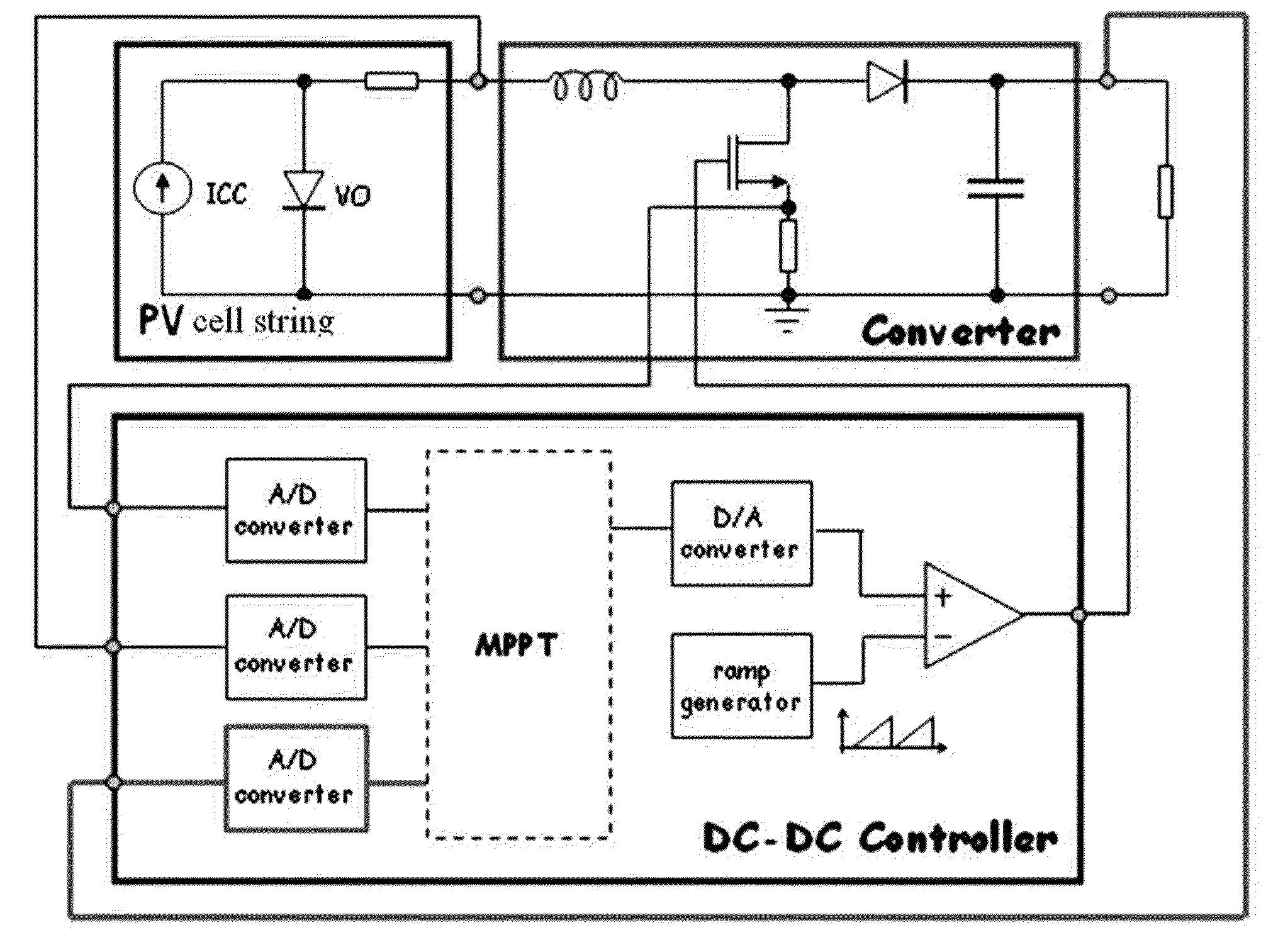
The patent describes a new structure for a photovoltaic energy conversion plant that improves the control of the working point to maximize the yield of electric power. The structure includes a distributed control system for groups of cells in each panel, which simplifies the control hardware and reduces the need for expensive components. Each panel has a DC bus and a DC-DC converter with a control circuit for optimizing the yield of power from the cells. The DC-DC converters are connected in series with the cells, and the overall cost of the structure is significantly lower than traditional centralized systems. The panels can be easily connected in a series-parallel interconnection design scheme, and the overall cost of the new architecture is further reduced because the DC-DC converters can function as by-pass diodes for the cells.

Problems solved by technology

By connecting in series all the cells of the array to the terminals of the panel, there are potential problems: if one or more cells of a panel are for some reason significantly less illuminated than the other cells, the whole series of panels would be limited to work at the current imposed by the underexposed cells; in the case of failure of one or more cells or of their complete obscuration, interruptions may take place (i.e., an open circuit may occur in the current path of the DC source represented by the panel).
The cost of such a central control and conversion appliance is not negligible.

Method used


Image

  • Multi-cellular photovoltaic panel system with DC-DC conversion replicated for groups of cells in series of each panel and photovoltaic panel structure
  • Multi-cellular photovoltaic panel system with DC-DC conversion replicated for groups of cells in series of each panel and photovoltaic panel structure
  • Multi-cellular photovoltaic panel system with DC-DC conversion replicated for groups of cells in series of each panel and photovoltaic panel structure

Examples


Embodiment Construction

[0064]In particular, in the exemplary embodiments described, a step-up or boost DC-DC converter is used for stabilizing the generated voltage though any other topology of DC-DC converter can be used such as a buck-boost converter or even a step-down converter.

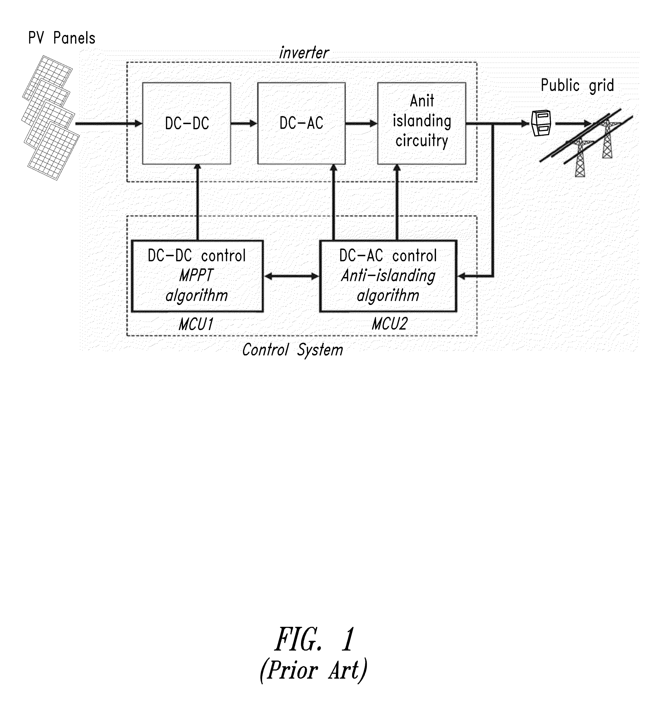
[0065]FIG. 5 shows a general block diagram of a photovoltaic conversion system 10 according to this disclosure for a grid-connected application. The system 10 includes an anti-islanding circuit 12 having connection / disconnection switches for connecting and disconnecting the system 12 from the public electricity grid under the control of a control circuit 14. The portion of the control block 14 that controls the anti-islanding system and the related connection / disconnection switches of the anti-islanding circuit 12 are accessory and unessential features of the photovoltaic conversion system.

[0066]FIG. 5 highlights a feature of the novel photovoltaic conversion system 12 employing one or more multi-cellular panels 16 that incorpo...


PUM


Abstract

A photovoltaic energy conversion system includes a distributed control structure for groups of cells of each multi-cellular panel, the components of which are entirely physically integrated in the photovoltaic panel. Each multi-cellular photovoltaic panel has a DC bus, supplied in parallel by a plurality of DC-DC converters, each provided with a controller that controls the working point of the photovoltaic cells coupled to the input of the DC-DC converter for a maximum yield of electric power by implementing a relatively simple MPPT algorithm. The controller includes a logic circuit and A / D converters of analog signals representing the input voltage and the input current generated by the group of cells that is coupled to the input of the DC-DC converter and optionally also of the output voltage of the converter, and a relatively simple D / A converter of the drive control signal of the power switch of the DC-DC converter.

Description

BACKGROUND[0001]1. Technical Field[0002]This invention relates to photovoltaic systems for converting light to electric energy using multi-cellular panels and more particularly to the maximization of the power delivered by each panel.[0003]2. Description of the Related Art[0004]A multi-cellular panel photovoltaic system for converting light to electric energy can be an isolated system (stand alone) with batteries for accumulating energy for delivering electric power even when the panels are not irradiated. In areas where public distribution mains are available, so-called grid-connected systems are preferably used, capable of delivering the electric energy generated to the public distribution mains through bidirectional meters.[0005]Even if the novel system of this disclosure is equally useful for grid-connected systems as well as for isolated systems, the ensuing description and the functional schemes used for illustrating it will refer to the case of a grid-connected system that, a...

Claims


Application Information

Patent Timeline
Patent Type & Authority Patents(United States)
IPC IPC(8): H02J1/00H02J3/00
CPCH02J1/10H02J3/383H02J2003/388H02M2001/007Y10T307/707Y02E10/58Y02E10/563H02J3/388H02J2300/24H02J3/381Y02A30/60Y02E10/56H02M1/007
Inventor RAGONESE, DOMENICOPULVIRENTI, FRANCESCOAIELLO, NATALENIGIDO, NICOLAILARDO, SANTODI FAZIO, SALVATORE
Owner STMICROELECTRONICS SRL
Learn More