Micro heat exchanger and its use as cooler for electronic components
a heat exchanger and electronic component technology, applied in the direction of lighting and heating apparatus, laminated elements, stationary tubular conduit assemblies, etc., can solve the problems of increasing the amount of waste heat generated and to be carried away, non-uniform inhomogeneous heat removal, and energy loss-dependent heat amounts, so as to achieve maximum heat transfer, increase heat transfer distance, and increase heat transfer distance
- Summary
- Abstract
- Description
- Claims
- Application Information
AI Technical Summary
Benefits of technology
Problems solved by technology
Method used
Image
Examples
first embodiment
[0034]FIGS. 3a and 3b show the components of a micro heat exchanger with arrangements according to the The micro heat exchanger comprises the carrier plate 11 shown in FIG. 3a with the above-mentioned inlet and outlet duct structures 1 or, respectively, 2, the separating wall 4 and the distribution volumes 5, 6 in the form of machined-in recesses as well as inlet 7 and respectively, outlet 8 in the form of penetrations. In addition, the carrier plate includes at its circumference around the above-mentioned recesses a circumferential groove 14 for receiving a cement and / or sealing means for sealing a cover plate 11 (see FIGS. 4a and 4b) disposed thereon. The passages 3 are machined into the cover foil 12 as grooves extending normal to the inlet and outlet duct structures 1 and 2 (for example, mechanically) wherein the area of their extension forms the above-mentioned heat transfer area 13. The corresponding cross-section which extends normally through the duct structures 1 and 2 at ...
second embodiment
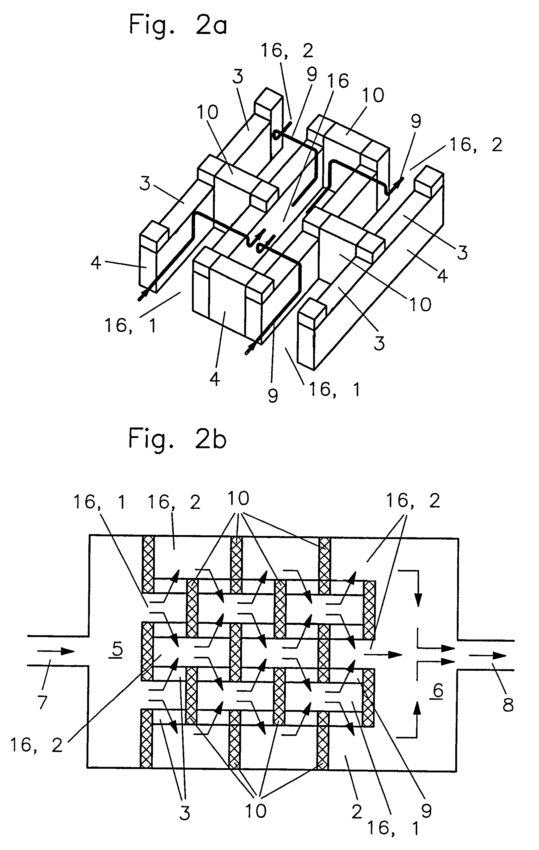
[0036]FIG. 4b shows a heat transfer area 13 with an arrangement of two oppositely arranged heat exchangers of the type described above. It is particularly suitable as a counter flow heat exchanger in connection with the second embodiment described above (see FIGS. 2a and 2b).
[0037]FIG. 5 on the other hand is a cross-sectional view similar to that of FIG. 4a of another embodiment. In this embodiment, no circumferential groove and no sealing means are provided to form a more compact structure. The carrier plate 11 and the cover foil 12 consist preferably of the same materials or materials which can thermally be joined preferably a metal, a metal alloy or a plastic and are joined in a fluid-tight manner preferably by diffusion welding. For avoiding excessive shear tensions at the joint 18, in this embodiment, the non-structured bottom area 17 of the carrier plate 11 is made as thin and therefore as elastically resilient as possible. Preferably, in this case, the height of the walls 4 a...
PUM
 Abstract
Description
Claims
Application Information
 - R&D
- Intellectual Property
- Life Sciences
- Materials
- Tech Scout
- Unparalleled Data Quality
- Higher Quality Content
- 60% Fewer Hallucinations
Browse by: Latest US Patents, China's latest patents, Technical Efficacy Thesaurus, Application Domain, Technology Topic, Popular Technical Reports.
© 2025 PatSnap. All rights reserved.Legal|Privacy policy|Modern Slavery Act Transparency Statement|Sitemap|About US| Contact US: help@patsnap.com


