Full reverse flow type heat recovery device

A heat recovery device and counter-flow technology, applied in indirect heat exchangers, heat exchanger types, heat exchange equipment, etc., can solve the problem of reducing heat exchange efficiency of heat exchangers, high heat exchanger manufacturing costs, and high equipment maintenance costs problems, to achieve the effect of reducing the difficulty of production, reducing the diameter of the equipment, and increasing the installation density

Active Publication Date: 2021-09-17
NANJING JUTUO CHEM TECH
View PDF7 Cites 0 Cited by
  • Summary
  • Abstract
  • Description
  • Claims
  • Application Information

AI Technical Summary

Problems solved by technology

[0002] Tube-and-tube heat exchangers are widely used as conventional equipment for syngas heat recovery. Due to the high concentration of hydrogen in the syngas, in order to avoid hydrogen corrosion of welds, it is necessary to use welding materials that are resistant to high temperature and strong hydrogen corrosion. , leading to higher production costs of heat exchangers and higher equipment maintenance costs
In addition, the structure of the tube-and-tube heat exchanger generally adopts a semi-counter-current structure, that is, only part of the heat exchange tube is a counter-flow heat exchange, while the other part is a downstream heat exchange, which reduces the heat exchange efficiency of the heat exchanger.

Method used


Image

  • Full reverse flow type heat recovery device
  • Full reverse flow type heat recovery device
  • Full reverse flow type heat recovery device

Examples


Embodiment Construction

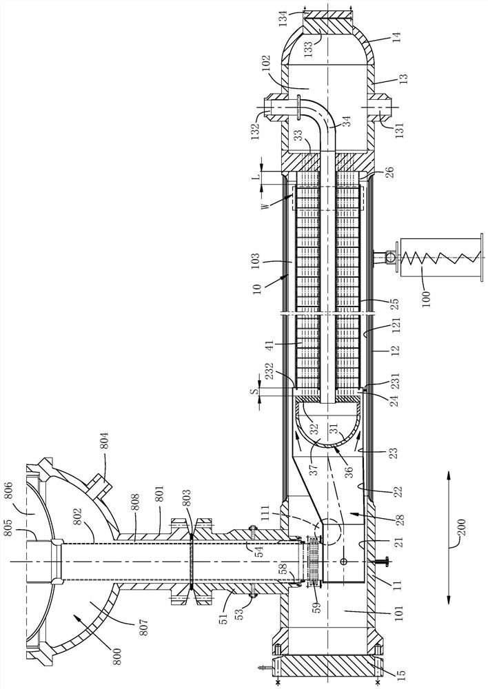
[0036] see figure 1 , figure 1 , the arrow 200 indicates the direction of the axis, which extends in the horizontal direction.

[0037] A full countercurrent heat recovery device, which includes a casing 10 extending along the axial direction, the casing includes a gas-side tube box 11, a composite cylinder 12 and a water-side tube box 13 connected in sequence, and the composite tube A divided tube sheet 33 is arranged between the body 12 and the water side tube box 13, a flat head 15 is installed at the end of the gas side tube box 11 away from the divided tube sheet, and a flat head 15 is installed at the end of the water side tube box 13 away from the divided tube sheet 33 There is a circular head 14, and a manhole 133 is opened in the center of the circular head 14, and a cover plate 134 is installed on the manhole 133, and the composite cylinder 12 is formed by laminating multiple layers of steel plates. The cylinder 12 is the bandaging cylinder in the prior art. A sli...


PUM


Abstract

The invention discloses a full reverse flow type heat recovery device. The heat recovery device comprises a shell extending in the axis direction, an inner cavity of the shell is divided into a heat exchange cavity and a water inlet cavity through a dividing tube plate, a heat exchange cylinder is arranged in the heat exchange cavity and comprises an air inlet cylinder and an inner cylinder which are connected together, and an air return cavity is formed between the heat exchange cylinder and the shell; a water return piece composed of an inner tube plate and an inner sealing head is arranged in the air inlet cylinder, and a water return cavity is formed between the inner tube plate and the inner sealing head; the end, facing the inner tube plate, of the inner cylinder is provided with an air inlet channel, and the inner cylinder communicates with the air inlet cylinder through the air inlet channel; an air outlet channel is formed in one end, facing the dividing tube plate, of the inner cylinder, and the inner cylinder communicates with the air return cavity through the air outlet channel; a tube nest is mounted in the heat exchange cylinder, one end of the tube nest communicates with the water return cavity through the inner tube plate, and the other end of the tube nest communicates with the water inlet cavity through the dividing tube plate; one end of a drain tube communicates with the water return cavity through the inner tube plate, and the other end of the drain tube is used as a refrigerant outlet. According to the heat recovery device, hydrogen corrosion can be reduced, the heat exchange efficiency can be improved, and the manufacturing cost can be reduced.

Description

technical field [0001] The invention belongs to the technical field of chemical equipment, in particular to a full countercurrent heat recovery device. Background technique [0002] Tube and tube heat exchangers are widely used as conventional equipment for syngas heat recovery. Since the syngas contains high concentration of hydrogen, in order to avoid hydrogen corrosion of welds, it is necessary to use welding materials that are resistant to high temperature and strong hydrogen corrosion. , resulting in higher manufacturing costs of the heat exchanger and higher equipment maintenance costs. In addition, the structure of the tube-and-tube heat exchanger generally adopts a semi-counter-current structure, that is, only part of the heat exchange tube is for counter-flow heat exchange, while the other part is for forward-flow heat exchange, which reduces the heat exchange efficiency of the heat exchanger. Contents of the invention [0003] In order to improve the heat exchan...

Claims


Application Information

Patent Timeline
Patent Type & Authority Applications(China)
IPC IPC(8): F28D7/00F28D7/06F28F9/02F28F9/22F28F9/26
CPCF28D7/00F28D7/06F28F9/02F28F9/22F28F9/26Y02P20/10
Inventor 卢健王雪林
Owner NANJING JUTUO CHEM TECH
Why Eureka
Try Eureka