Ion guide device, ion reactor, and mass analyzer

a technology of mass analyzer and guide device, which is applied in the direction of mass spectrometer, stability-of-path spectrometer, separation process, etc., can solve the problems of affecting the speed of analysis, and affecting the efficiency of structure analysis of measurement samples, so as to reduce the speed of analysis of structure samples, the effect of reducing throughput and efficient causing the reaction during transportation

Active Publication Date: 2011-11-01
HITACHI LTD
View PDF14 Cites 45 Cited by
  • Summary
  • Abstract
  • Description
  • Claims
  • Application Information

AI Technical Summary

Benefits of technology

[0027]In such configuration, a radio frequency voltage obtained by modulating the radio frequency voltage amplitude is applied, and with this modulation of the radio frequency electric field the transfer speed of an ion is adjusted. The amplitude of the radio frequency voltage is controlled so as to periodically change, and the resulting radio frequency voltage is applied so that the phases at the adjacent electrodes differ from each other by a certain value. Generating a pseudopotential in the radial direction by the radio frequency voltage so as to focus ions is the same as the conventional ion guide or ion trap. However, by modulating the radio frequency voltage amplitude, the ups and downs of the pseudopotential are also generated in the axial direction. Furthermore, a field where the bottom of the ups and downs of the pseudopotential moves at a certain speed is formed, whereby ions are captured by an ion packet of the bottom of the ups and downs of this pseudopotential and the ions are transported along with the movement of the ion packet. The ion packet caused by this pseudopotential features the capability of capturing the positive ions and negative ions at the same time. Moreover, the frequency for modulating the amplitude determines the transfer speed of the ion packet, so that the transit time of the ions inside the charged particle reaction cell can be adjusted.
[0030]According to the present invention, since the incoming and outgoing of ions are not controlled with the wall electrodes or the like as in the ordinary ion trap, ions can be incident to the charged particle reaction cell at intervals from several milliseconds to several hundreds of microseconds and also the residence time of ions can be extended by about 10 msec or more. Furthermore, by putting the positive ions and negative ions into the same ion packet, 10 msec or more required for the reaction time of the charged particles in ETD can be secured. Moreover, since this is a method in which the incident positive and negative ions pass through the interior of the ion trap and are sequentially ejected with their incident order being kept, it is possible to efficiently cause the reaction during the transportation.
[0031]In this way, in a charged particle reaction device using a radio frequency ion trap, the speed of the charged particle reaction can be accelerated. The lowered throughput and mass resolution, which are the problems in implementing the charged particle reaction, can be solved, and the speed of the structure analysis of a measurement sample can be accelerated.

Problems solved by technology

Since the obtained information represents macroscopic quantities of the mass to charge ratios, it is difficult to obtain information on internal structure by a single mass analysis.
Therefore, a pretreatment using an enzyme or the like is necessary, which hampers high-speed analysis.
Further, when CID or IRMPD is used for post-translationally modified biomolecules, side chains involved in the post-translational modification tend to be easily cleaved.
However, important information on modification sites concerning which amino acids are modified is lost.

Method used


Image

  • Ion guide device, ion reactor, and mass analyzer
  • Ion guide device, ion reactor, and mass analyzer
  • Ion guide device, ion reactor, and mass analyzer

Examples


embodiment 1

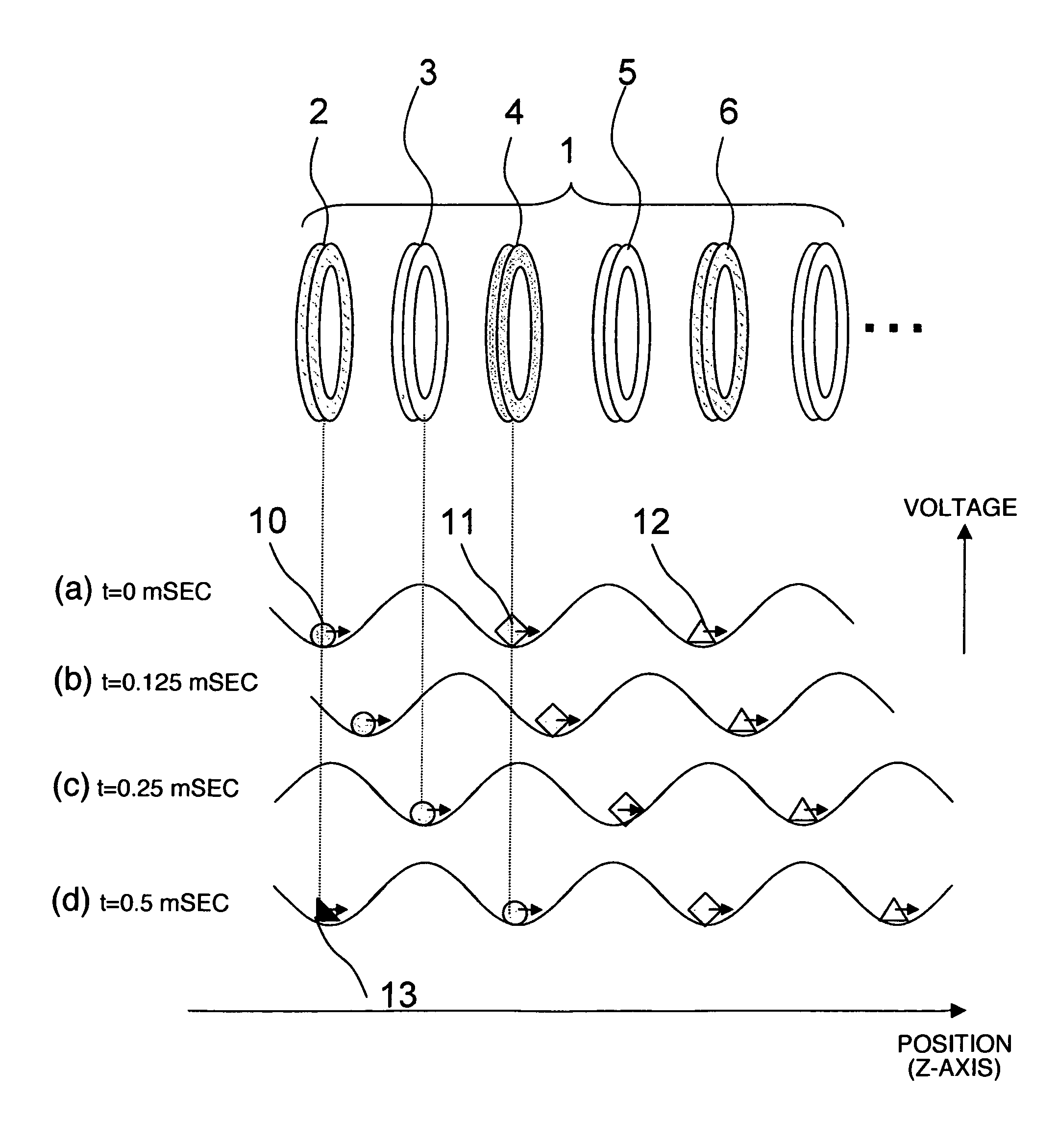
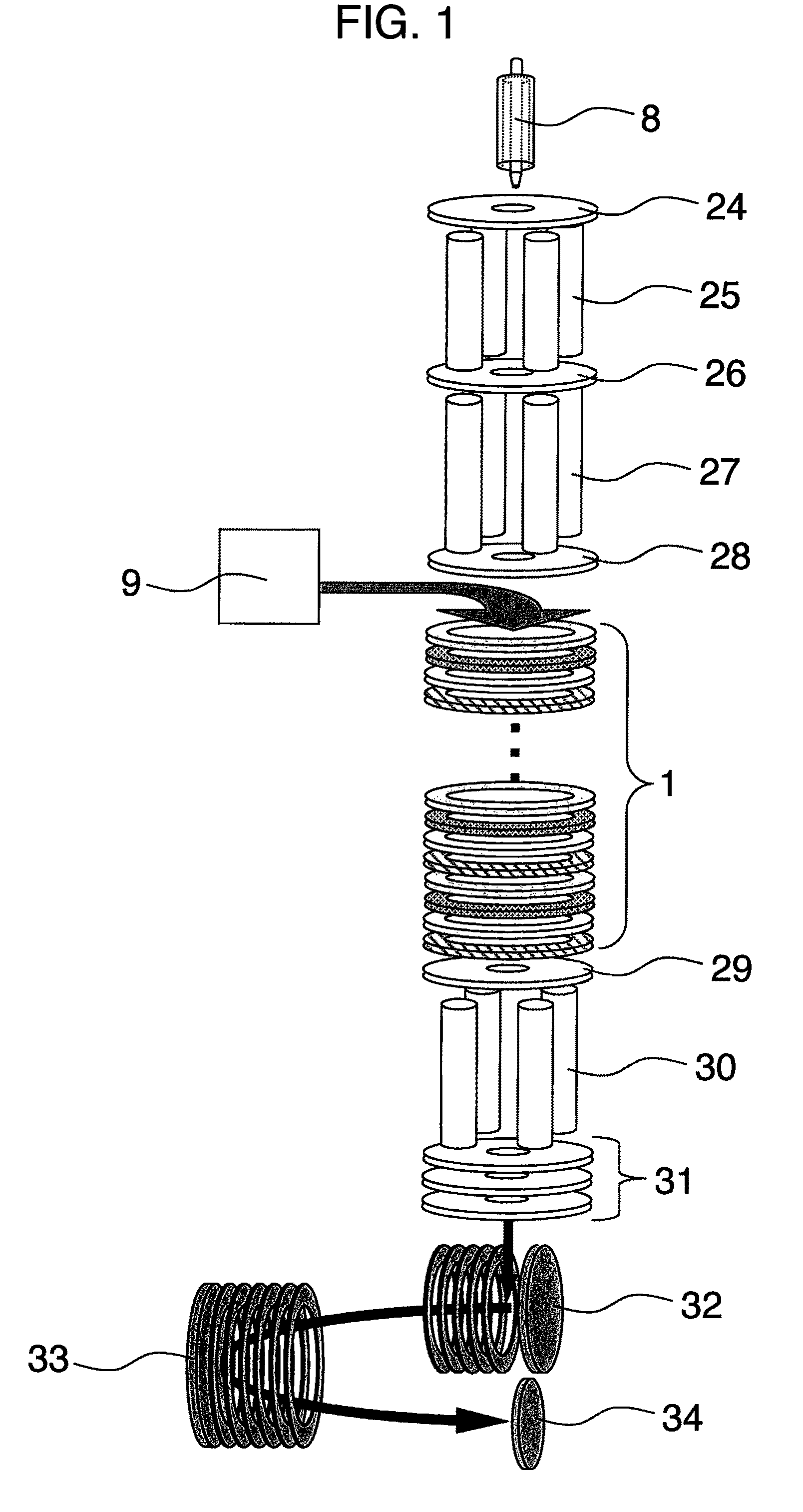
[0046]FIG. 1 is a schematic diagram for explaining an embodiment of a mass spectrometer provided with a unit for an electron transfer dissociation (ETD) reaction, which is a charged particle reaction of positive ions and negative ions in an ion trap. First, the overall flow of the analysis is described, followed by the detail description of the present disclosure.

[0047]For a sample of analyte, a sample separated by liquid chromatograph or the like is ionized in a positive ion source 8. The ionized sample is incident upon a quadrupole ion guide part 24 and 25 inside a vacuum device, and passes therethrough and is introduced into a linear ion trap part 26 to 28. He gas, Ar gas, or the like is introduced into the ion trap part, where the sample ion is cooled by collision with the gas. In the linear ion trap part, the accumulation, separation, and ejection of ions are performed and the ejected ions are incident to an electron transfer dissociation cell. The electron transfer dissociatio...

embodiment 2

[0063]FIG. 6 is a schematic diagram for explaining an embodiment of a mass spectrometer provided with a unit for an Electron Capture Dissociation (ECD) reaction, which is the charged particle reaction between a positive ion and an electron in an ion trap. The overall flow of the analysis is the same as the description of FIG. 1. In the electron capture dissociation reaction cell, electrons are emitted from an electron source 15 to cause an Electron Capture Dissociation (ECD) reaction while positive ions incident upon the plurality of electrodes 1 each having a circular hole opened therein are being captured.

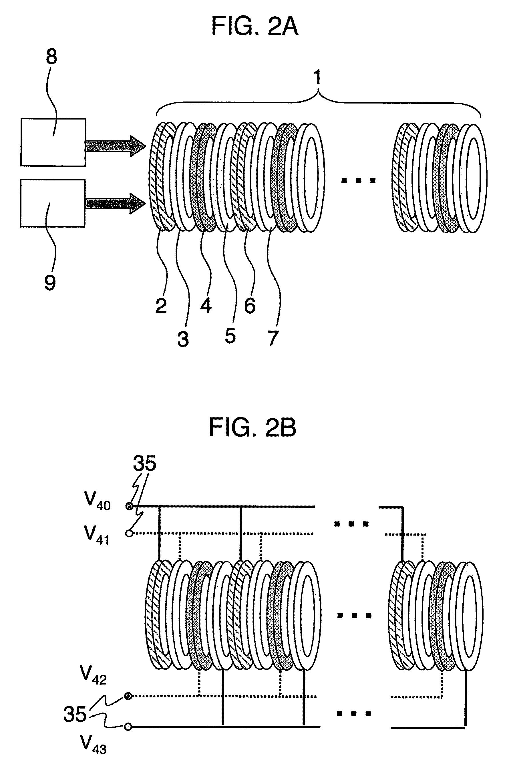
[0064]FIG. 7 illustrates the detail of the electron capture dissociation reaction cell. In the structure comprising the plurality of electrodes 1 each having a circular hole opened therein, a method for applying a radio frequency voltage to the plurality of electrodes 1 each having a circular hole opened therein is the same as the example of FIG. 2A to FIG. 5. The cylindrical mag...


PUM


Abstract

A charged particle reaction cell of the present invention has a serially-arranged plurality of ring electrodes, wherein a modulated radio frequency voltage obtained by modulating the amplitude of a radio frequency voltage is applied, whereby ions are captured at the bottom of the ups and downs of a formed pseudopotential and are transferred with the move of the pseudopotential. In the charged particle reaction cell, the time required for the charged particle reaction can be secured and also the problem of the decrease of the throughput or the mass resolution can be solved, and the speed of the structure analysis of a measurement sample can be accelerated.

Description

INCORPORATION BY REFERENCE[0001]The present application claims priority from Japanese Patent Application No. 2005-341365 filed on Nov. 28, 2005, the content of which is hereby incorporated by reference into this application.TECHNICAL FIELD[0002]The present invention relates to a method and device for analysis of sequence structures of biological macromolecules with the use of mass spectrometry.BACKGROUND OF THE INVENTION[0003]In mass spectrometry, sample molecules are ionized and introduced into a vacuum (or ionized in a vacuum), and mass to charge ratios of target molecular ions are measured by measuring movements of the ions in an electromagnetic field. Since the obtained information represents macroscopic quantities of the mass to charge ratios, it is difficult to obtain information on internal structure by a single mass analysis. Accordingly, a method called tandem mass spectrometry is used. That is, sample ions are isolated or selected in the first mass analysis. These ions are...

Claims


Application Information

Patent Timeline
Patent Type & Authority Patents(United States)
IPC IPC(8): H01J49/42
CPCH01J49/065H01J49/4235
Inventor SATAKE, HIROYUKIBABA, TAKASHIWAKI, IZUMI
Owner HITACHI LTD
Why Eureka
Try Eureka