Method for increasing fatigue notch capability of airfoils

a technology of airfoil and notch capability, which is applied in the field of fatigue resistance and damage tolerance components, can solve the problems of reducing the life of parts, repair or replacement, and prone to cracking from fatigue and damage, so as to reduce the propagation of cracks and avoid deformation of the leading edge

Inactive Publication Date: 2011-11-08
GENERAL ELECTRIC CO
View PDF55 Cites 16 Cited by
  • Summary
  • Abstract
  • Description
  • Claims
  • Application Information

AI Technical Summary

Benefits of technology

[0004]The above shortcomings of the prior art, among others, are addressed by the present invention, which according to one aspect provides a method of reducing crack propagation in an airfoil, including: providing an airfoil having a root spaced apart from a tip, spaced-apart leading and trailing edges, a suction side extending from the leading edge to the trailing edge, and an opposed pressure side extending from the leading edge and the trailing edge; supporting the airfoil against bending loads; and burnishing the airfoil using a burnishing element, so as to create at least one burnished section of residual compressive stress, the at least one burnished section being located adjacent the leading edge and spaced from the leading edge by an offset distance selected so as to avoid deformation of the leading edge.
[0005]According to another aspect of the invention, an airfoil for a gas turbine engine includes: a root spaced apart from a tip, spaced-apart leading and trailing edges, a suction side extending from the leading edge to the trailing edge, and an opposed pressure side extending from the leading edge and the trailing edge, wherein a thickness of the airfoil is defined between the pressure side and the suction side; and at least one burnished section of residual compressive stress extending inward from a selected one of the pressure side and the suction sides. The burnished section is located adjacent the leading edge and spaced from the leading edge by an offset distance selected so as to avoid deformation of the leading edge.

Problems solved by technology

Various metallic, ceramic, and composite components, such as gas turbine engine fan and compressor blades, are susceptible to cracking from fatigue and damage (e.g. from foreign object impacts).
This damage reduces the life of the part, requiring repair or replacement.
However, shot peening is detrimental to the surface finish and has a lot of variation in its intensity even with industry standard control systems in place.
Parts like compressor airfoils lose their efficiency with rough surface finishes produced by shot peening.
Laser shock peening cans be expensive due to the required specimen preparation, equipment used, and personnel training requirements.
Furthermore, both shot peening and laser shock peening can be relatively slow processes.

Method used


Image

  • Method for increasing fatigue notch capability of airfoils
  • Method for increasing fatigue notch capability of airfoils
  • Method for increasing fatigue notch capability of airfoils

Examples


Embodiment Construction

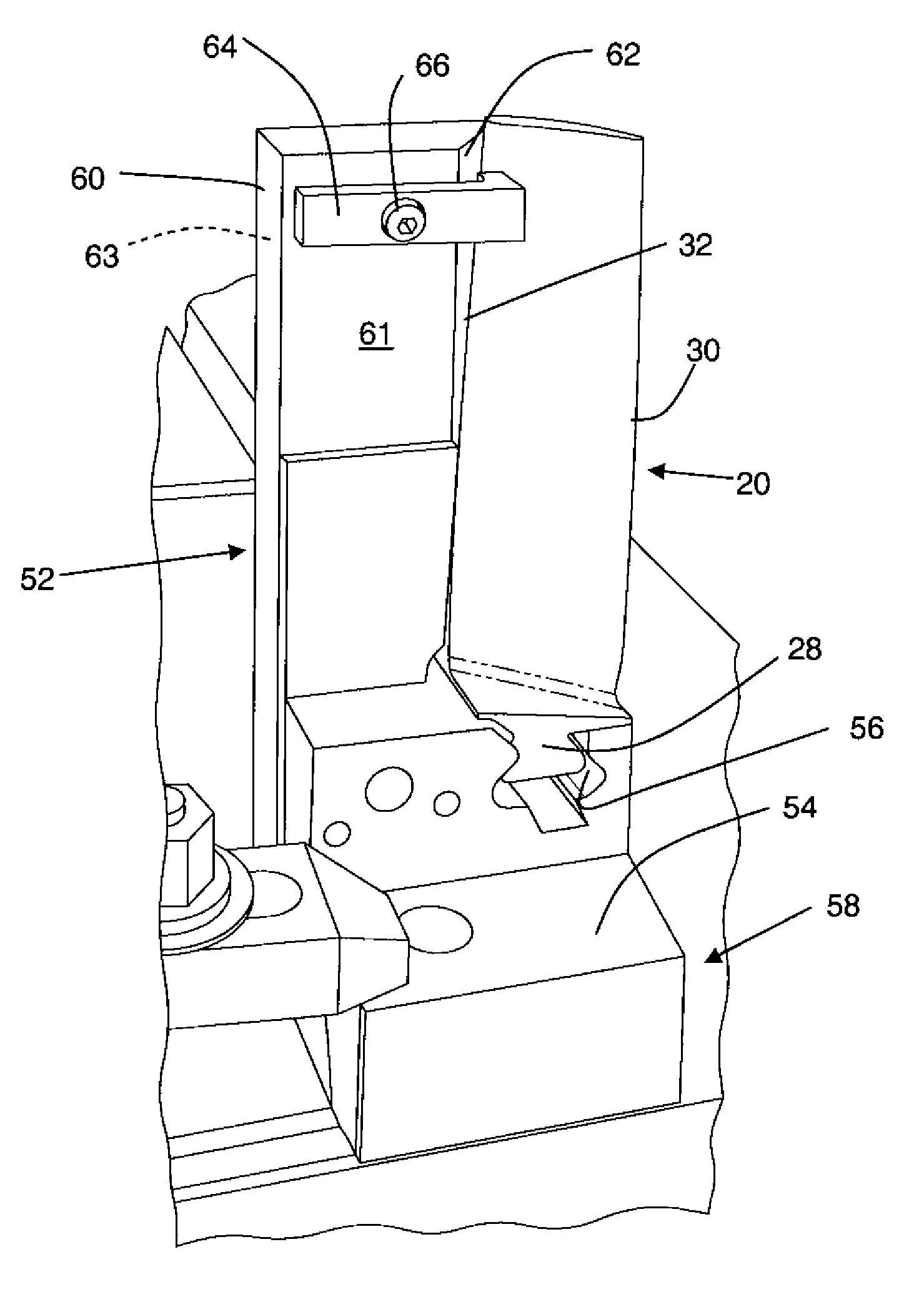
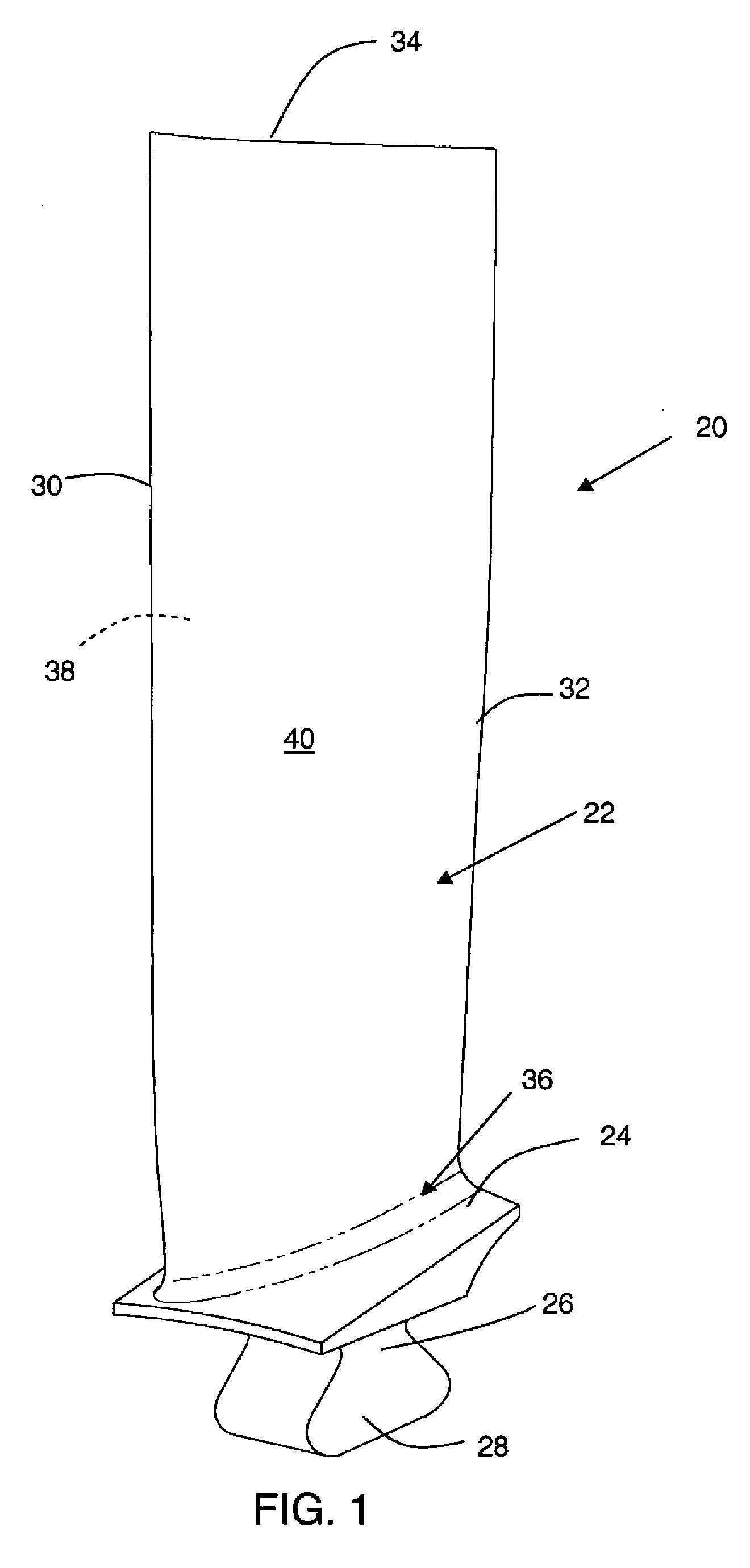
[0013]Referring to the drawings wherein identical reference numerals denote the same elements throughout the various views, FIG. 1 illustrates an exemplary gas turbine engine compressor blade 20, before treatment. This component is used merely as an example of a part to which the method of the present invention may be applied the present invention is equally applicable to other types of components susceptible to cracking from fatigue or damage, such as compressor stator vanes, fan blades, turbine blades, shafts and rotors, stationary frames, actuator hardware and the like. Such components may be made from metal alloys, ceramics, or composite materials (e.g. carbon fiber composites). Typically, such blades are made of an alloy based on titanium, iron, or nickel. Examples of such alloys that are commercially available include Ti6-4, Ti 6-2-4-2, A-286, C 450, and In 718. The compressor blade 20 includes an airfoil 22, a platform 24, and a shank 26. In this particular example the shank ...


PUM

PropertyMeasurementUnit
offset distanceaaaaaaaaaa
diameteraaaaaaaaaa
hydrostatic pressureaaaaaaaaaa

Abstract

A method of reducing crack propagation in an airfoil includes: providing an airfoil having a root spaced apart from a tip, spaced-apart leading and trailing edges, a suction side extending from the leading edge to the trailing edge, and an opposed pressure side extending from the leading edge and the trailing edge, supporting the airfoil against bending loads; and burnishing the airfoil using a burnishing element, so as to create at least one burnished section of residual compressive stress, the at least one burnished section being located adjacent the leading edge and spaced from the leading edge by an offset distance selected so as to avoid deformation of the leading edge.

Description

BACKGROUND OF THE INVENTION[0001]This invention relates generally to fatigue-resistant and damage-tolerant components and methods of producing such components.[0002]Various metallic, ceramic, and composite components, such as gas turbine engine fan and compressor blades, are susceptible to cracking from fatigue and damage (e.g. from foreign object impacts). This damage reduces the life of the part, requiring repair or replacement.[0003]It is known to protect components from crack propagation by inducing residual compressive stresses therein. Methods of imparting these stresses include shot peening, laser shock peening (LSP), pinch peening, and low plasticity burnishing (LPB). These methods are typically employed by applying a “patch” of residual compressive stresses over an area to be protected from crack propagation, for example a leading edge of a gas turbine engine compressor blade. However, shot peening is detrimental to the surface finish and has a lot of variation in its inten...

Claims


Application Information

Patent Timeline
Patent Type & Authority Patents(United States)
IPC IPC(8): B21D53/78B21K3/04
CPCB23P6/002B23P9/02B24B39/00C21D7/04C21D7/08Y10T29/479Y10T29/49336Y10T29/471Y10T29/47
Inventor LUNA, ALBERTOMILLER, JOSHUA LEIGHDINGWELL, WILLIAM TERENCEBRUNCK, MICHAEL JAYIMHOFF, WILLIAM LEEMONCELLE, PAULLOMBARDO, DALE ROBERTWOODFIELD, ANDREW PHILIP
Owner GENERAL ELECTRIC CO
Why Eureka
Try Eureka