Anterior lumbar lag plate

a technology of lag plate and anterior lumbar disc, which is applied in the field of anterior lumbar fusion, can solve the problems of high non-union rate and failure rate, difficult to achieve anterior lumbar fusion, and long procedures with significant morbidity, and achieve the effect of maximizing the effectiveness of the anterior lumbar fusion devi

Inactive Publication Date: 2011-11-08
STRYKER EURO OPERATIONS HLDG LLC
View PDF15 Cites 15 Cited by
  • Summary
  • Abstract
  • Description
  • Claims
  • Application Information

AI Technical Summary

Benefits of technology

[0010]The design of the new Anterior Lumbar Lag Plate (hereinafter “lumbar plate”) takes into account the uses for the plate and the flaws of its predecessors, and maximizes its effectiveness as an anterior lumbar fusion device. The new lumbar plate is used in lag mode wherein the screws are placed in a mode that allows for dynamic compression, but no distraction and therefore this plate also functions as a tension band.
[0011]More specifically, when the L5-S1 and bone graft therebetween go into compression, the bone screw extending with clearance through the lumbar plate can incline downward a few degrees while the lumbar plate fixed to S1 remains substantially unmoved. This allows a dynamic compression load on the bone graft which replaced the disc, and enhances better spinal fusion between L5,S1 and the bone graft.
[0013]The new instrumentation allows for use of a single step drill or awl through a drill guide, followed by placement of each self-threading screw through a drill guide. This drill guide does not have to be moved or changed in position between the steps of forming the holes and placing the screws. This avoids the inconvenience and requirement in prior systems of removing the drill guide before placing the screws. This also avoids the risk of incorrect final alignment of holes of the plate and the vertebrae. The new lumbar plate and method of placement is very surgeon friendly, shortens operative time and adds accuracy. Also, by allowing use of a drill or an awl as alternate methods of screw placement, the surgeon has a choice of the techniques for preparing the bone to accept a screw, depending on the condition and structure of the vertebra bone made visible by the surgery.
[0014]In patients with relatively hard bone structure, drilling before screw placement can easily accomplish secure purchase. In osteroporotic bone, an awl may be selected to compact the bone around the screw hole before screw placement for achieving more secure screw purchase.
[0016]The present invention further includes a unique locking system to prevent or substantially restrict unscrewing of the bone screws which attach the new lumbar plate to L4-L5, L5-S1 or L4-L5-S1. In the new locking system, a thin plate is fastened to the anterior surface of the lumbar plate where it overlies all or at least a part of the heads of the implanted bone screws. In a first embodiment of this locking system, the exposed anterior surface of the lumbar plate includes a recess or pocket into which the locking plate is positioned, so that the resulting assembly of lumbar plate and locking plate has a generally smooth anterior surface. In a second embodiment of this locking system, the locking plate sits externally of the anterior surface of the lumbar plate but this locking plate still partially or fully overlies the heads of the bone screws and thus prevents these screws from unscrewing. In either embodiment, the posterior side of the locking plate can include optional projections which are extended into the hexagonal recesses of hex head bone screws, where the projections serve to assure proper seating of the lock plate.

Problems solved by technology

In the past, performing anterior fusion with total disc excision has been problematic without using posterior instrumentation.
There was the “cage rage” of the 1990's which lead to high non-union rates and failures.
This subjected patients to long procedures with significant morbidity.
These techniques are difficult and require significant nerve root retraction, which places the root at risk.
There has also been a high rate of non-union because of inadequate disc space preparation from the posterior approach.
Unfortunately, current instrumentation systems for anterior fusion, such as the Danek triangular plate and the Synthese plate, have serious flaws.
Firstly, a fixed angle device does not allow any dynamic loading in compression and may stress shield the graft, possibly leading to non-union.
Secondly, the locking mechanism with the Synthese plate fixes the screw to the plate and does not allow the plate to be lagged to the bone securely.
This can lead to prominence of the plate, which can be a problem in this location, since the plate is placed under the great vessels at L4-L5.
Also, the surgeon has no feel for the purchase of the screws to the bone.

Method used


Image

  • Anterior lumbar lag plate
  • Anterior lumbar lag plate
  • Anterior lumbar lag plate

Examples


second embodiment

[0078]FIGS. 18, 19 and 20 illustrate the locking plate, namely plate 60 with its attachment screw 61 for engagement in threaded hole 20 of the lumbar plate 10x. FIG. 19 shows that the bottom of locking plate 60 has protrusions 62a, 62b. These protrusions extend down into the recess of the hex head screws 15a, 15b when the locking plate 60 is secured by screw 61 to the lumbar plate 10x. As with the previously described locking plate 52, when locking plate 60 is installed, it bars the screws 15a and 15b from unscrewing and rising axially, because the screw heads engage the bottom of the locking plate and cannot move axially, and because each protrusion 62a,62b extends into the recess of hex head screw 15a, 15b respectively.

[0079]D. Method of Employing the New Anterior Lumbar Lag Plate for Attachment to L4, L5, S1

[0080]The method of employing the new lumbar plate has been generally described in the above Summary of the Invention and in the section entitled Drill Guide Assembly, and fur...

first embodiment

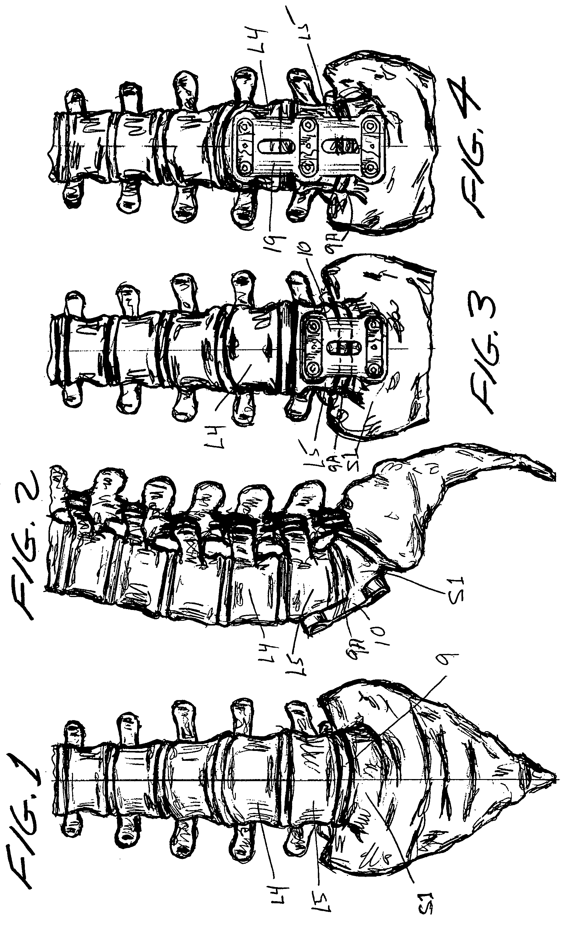
[0083]3. Lumbar plate 10 with upper attached drill guide 30 is then placed upon the anterior surface of the adjacent vertebrae selected, which would be adjacent L4-S1 for the new lumbar plate,

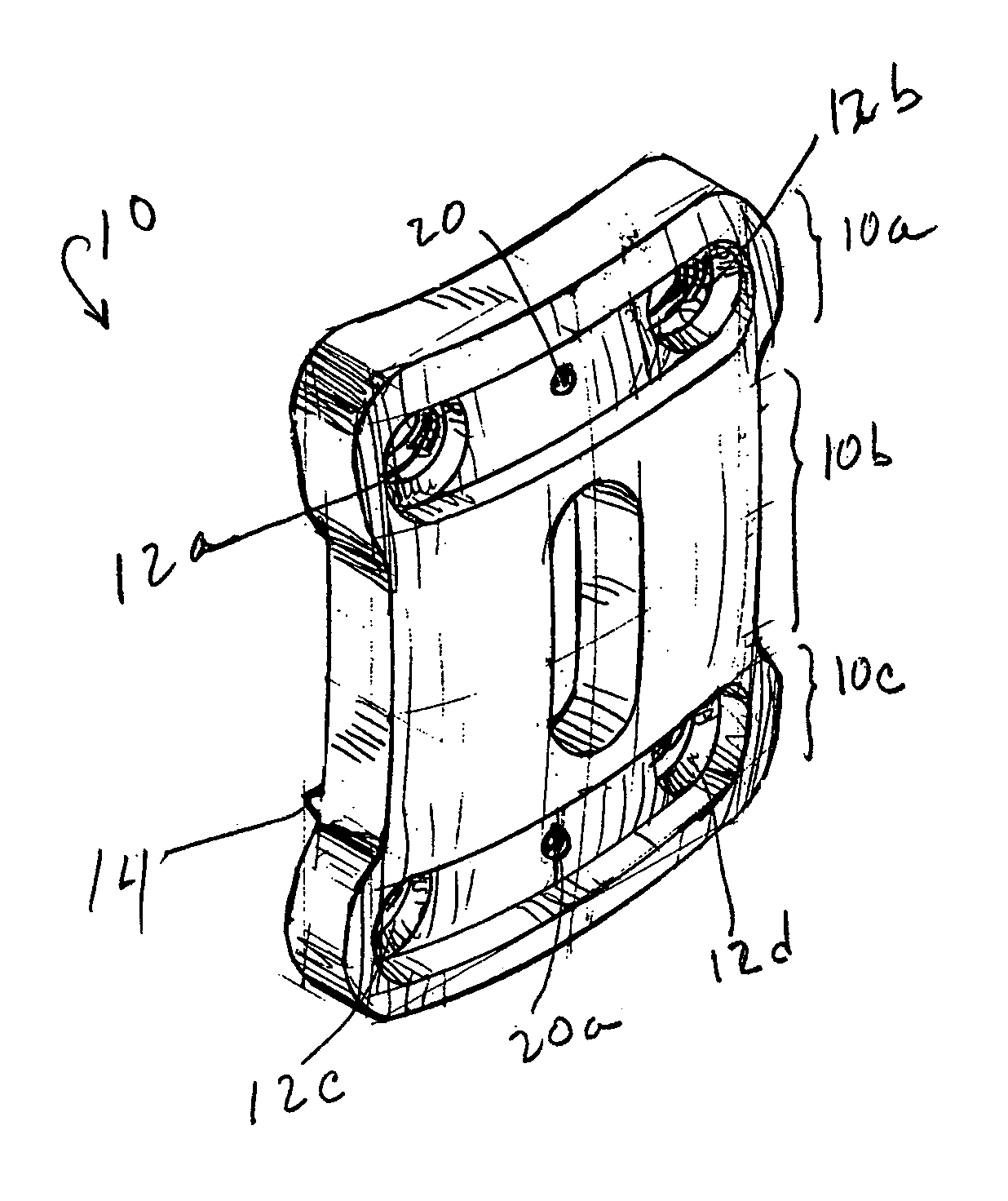
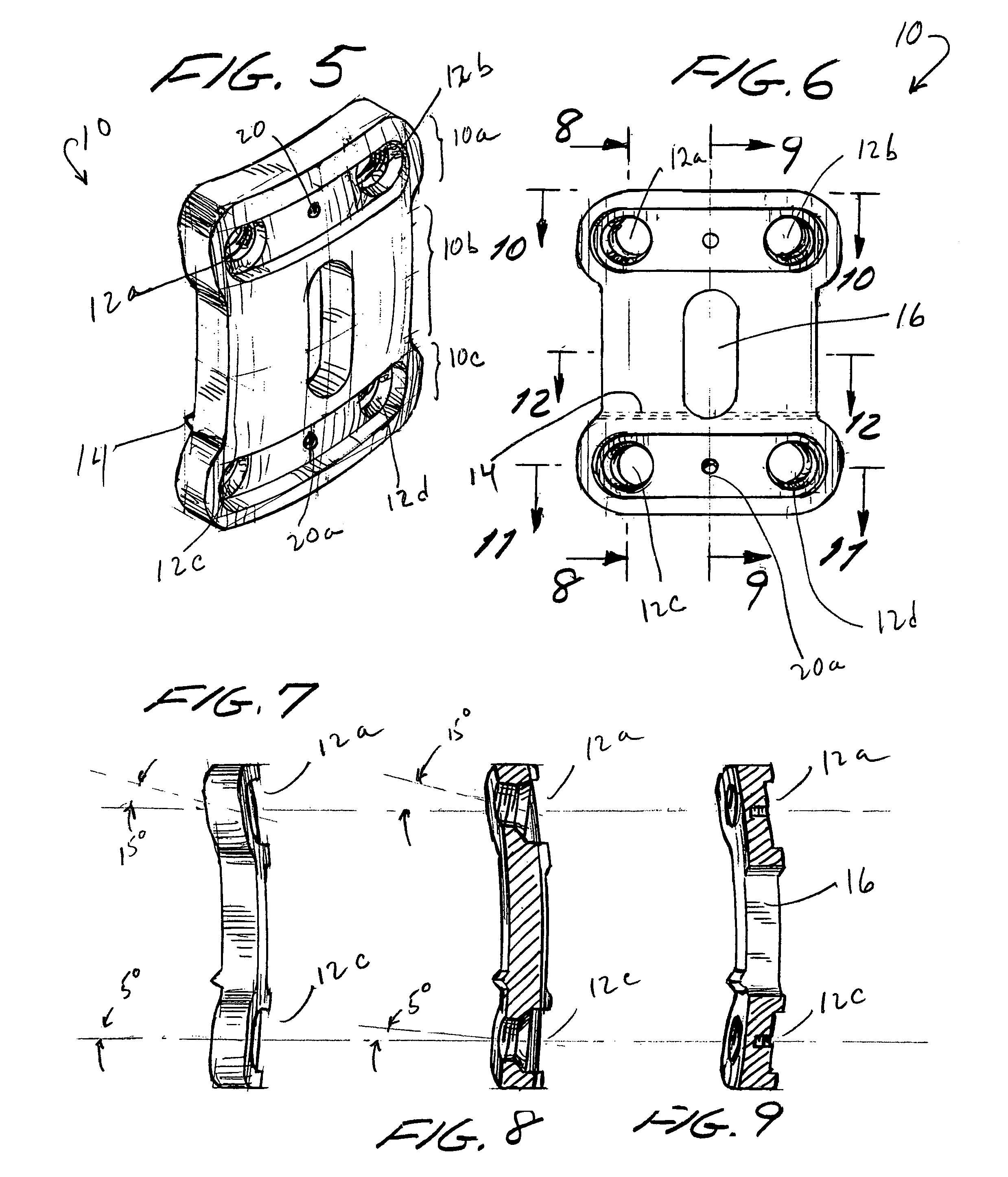
[0084]4. The two holes 35 and 36 in upper drill guide 30 are aligned with the two holes 12a, 12b in lumbar plate 10, which are now positioned correctly for forming holes in L4. A drill or awl is extended through the drill guide hole 36 and lumbar plate hole 12b and thence into L4 forming the hole therein. The drill or awl is then removed and a self-threading bone screw 15b is driven into hole 12b. Next, hole 12a is similarly formed via drill guide 30 and a self-threading bone screw 15a is installed. A typical bone screw into L5 extends through the lumbar plate hole 12a with sufficient clearance to allow about 15° of angulation of the screw relative to the plate. Consequently, during subsequent healing and bone regeneration, the slight movement or orientation change of the plate will allow loadi...


PUM


Abstract

An anterior lumbar plate for attachment with bone screws to selected vertebrae of a person's spine is combined: (a) with separate L5 and S1 drill guides separately and removably attachable to the lumbar plate, and (b) with lock plates removably attachable to the lumbar plate to prevent unscrewing of installed bone screws. This invention further provides a method for implanting and locking in place the L5 and S1 bone screws. This invention is adaptable for L4-L5, L4-L5-S1, and L5-S1 lumbar plates.

Description

I. BACKGROUND OF THE INVENTION[0001]A. Field of the Invention[0002]The present invention relates to spinal fusions and more particularly to an anterior approach implant system for fixing a stabilizing appliance to the L4-L5, L5-S1 and L4-L5-S1 vertebrae.[0003]B. Prior Art[0004]Over 200,000 spinal fusions are performed each year in the United States, with the L4-L5 and L5-S1 disc spaces being the most commonly fused. The indications for fusion range from traumatic instability to degenerative spinal stenosis. Procedures which require decompression in addition to fusion are most commonly performed posteriorly. Fusions performed for primarily mechanical axial back pain from degenerative disc disease are done anteriorly.[0005]In the past, performing anterior fusion with total disc excision has been problematic without using posterior instrumentation. There was the “cage rage” of the 1990's which lead to high non-union rates and failures. Surgeons then began to perform 360s or anterior an...

Claims


Application Information

Patent Timeline
Patent Type & Authority Patents(United States)
IPC IPC(8): A61B17/80
CPCA61B17/1728A61B17/7059A61B17/8042A61B17/1757
Inventor DUBE, MICHAEL A.
Owner STRYKER EURO OPERATIONS HLDG LLC
Why Eureka
Try Eureka