Longitudinal flying wing aircraft

a flying wing aircraft and longitudinal technology, applied in the direction of wing shapes, fuselages, transportation and packaging, etc., can solve the problems of low aerodynamic efficiency of such aircraft, the integral rigid airlifting body of tailess flying wing aircraft cannot meet several simultaneous and contradictory problems, and achieve the effect of increasing the natural longitudinal dynamic stability of longitudinal flying wing aircra

Active Publication Date: 2011-11-15
DIZDAREVIC FARUK +1
View PDF35 Cites 20 Cited by
  • Summary
  • Abstract
  • Description
  • Claims
  • Application Information

AI Technical Summary

Benefits of technology

[0010]The “Longitudinal Flying Wing Aircraft” idea provides for the following applications and advantages:
[0011]a) an opportunity to design and produce large, high-lift-capacity, long-range, high-subsonic, and transonic hybrid flying wing aircraft that are having a natural longitudinal stability required for commercial passenger and cargo transport with airlifting bodies that are defined with efficient aft-camber airfoils.
[0012]b) an opportunity to design and produce large, high-lift-capacity, long-range, high-subsonic, and transonic manned hybrid flying wing aircraft for military purposes with a low visual, radar, and infra-red reflection that are having a natural longitudinal stability when airlifting bodies are defined with efficient aft-camber airfoils

Problems solved by technology

Unfortunately, no such idea has risen up to a sufficiently high level to meet safety requirements and official regulations for civil air transportation with competitive aerodynamic efficiencies relative to classical concept aircraft at high subsonic speeds.
There have been two main obstacles that resulted with such outcome including difficulties related to attaining the efficient longitudinal stabilization and pitch control of a large airlifting body, as well as the effective accommodation of bulky payload within the airlifting body that is designed with thin efficient airfoils.
The integral rigid airlifting body of tailess flying wing aircraft can not meet several simultaneous and contradictory requirements including natural dynamic and static stability when the airlifting body is designed with efficient aft camber airfoils that have air pressure center shifted in aft direction while having inability to deploy trailing edge devices for extra lift production at low sped during take-off and landing due to high negative pitch momentum.
The low aerodynamic efficiency of such aircraft is especially pronounced at high subsonic and transonic speeds.
If the integral airlifting body of a tailess flying wing aircraft was designed with efficient aft camber airfoils, the aircraft gravity center would need to be shifted in aft direction behind the neutral point in order to satisfy the static stability of aircraft when trailing edge devices for aerodynamic lift regulation being in their neutral position, thus such aircraft being naturally dynamically unstable, hence not satisfying safety regulations for civil air transportation.
In both cases, trailing edge devices for extra lift production can not be used due to a high negative pitch momentum that would be generated, hence requiring a high attack angle during approach to the airport and landing phase, thus additionally jeopardizing the flight safety and ride quality of such aircraft.
Military bomber B-2 is an example of a dynamically unstable tailess flying wing aircraft that has been fully developed so far though at extremely high production cost with limited range and speed, as well as low flight safety, all of which are the reasons for a low number of units that have been manufactured.
Intensive research over the past 15 years that has involved a significant number of experts in the areas of theoretical and applied aerodynamics, as well as computational analysis and wind tunnel testing have not produced a desirable outcome to simultaneously satisfy a required level of flight safety and competitive aerodynamic efficiency for civil air transportation at high subsonic speeds.
However, both solutions can not provide for a sufficient distance of the tailplane behind the large front airlifting body to allow for the application of efficient aft camber airfoil on the front airlifting body with a reasonable surface area of the tailplane due to a large semi-elliptical aft section of the front airlifting body that does not shift enough jet engine covers with stabilizing surfaces in aft direction, while simultaneously significantly increasing the area of the front airlifting body, which needs to be longitudinally stabilized.
In addition, the thick turbulent boundary layer over the upper surface of the front airlifting body in front of jet engine air intake is significantly reducing the jet engine efficiency of the “Tailed Flying Wing Aircraft” when compared with the efficiency of the jet engines of classical concept aircraft, which are positioned in front of wings, hence encountering a free and undisturbed airflow.
However, still a large wetted area of the tailplane when compared to classical concept aircraft, which does not produce lift or producing even a small amount of negative lift, as well as the parasite wetted area of fin with rudder and jet engine pylons with nacelles that are not contributing to lift production or longitudinal stabilization of aircraft may not be resulting with overwhelming advantages of flying wing idea over the classical concept aircraft with fuselage at high subsonic speeds.

Method used


Image

  • Longitudinal flying wing aircraft
  • Longitudinal flying wing aircraft
  • Longitudinal flying wing aircraft

Examples


Embodiment Construction

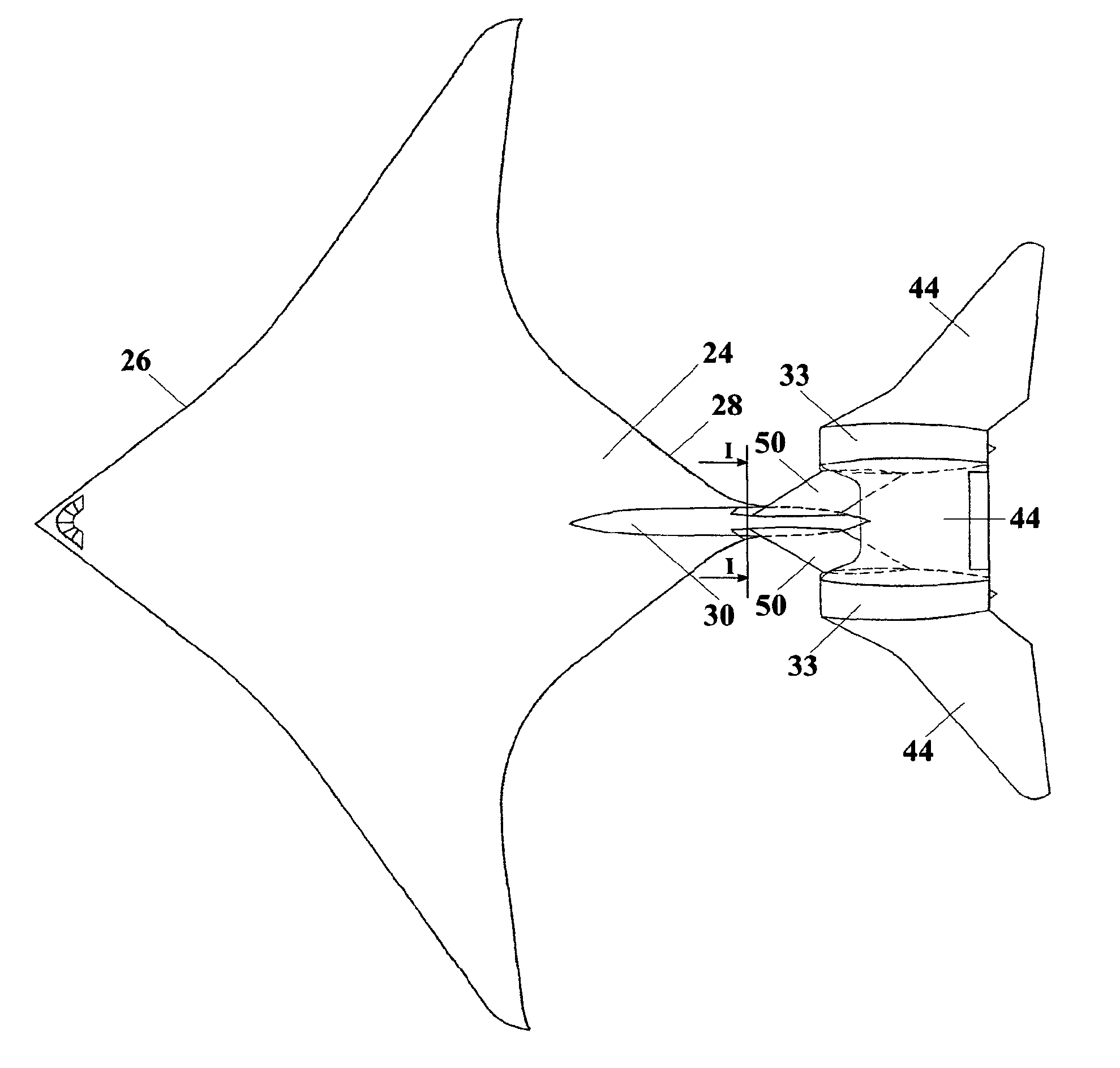
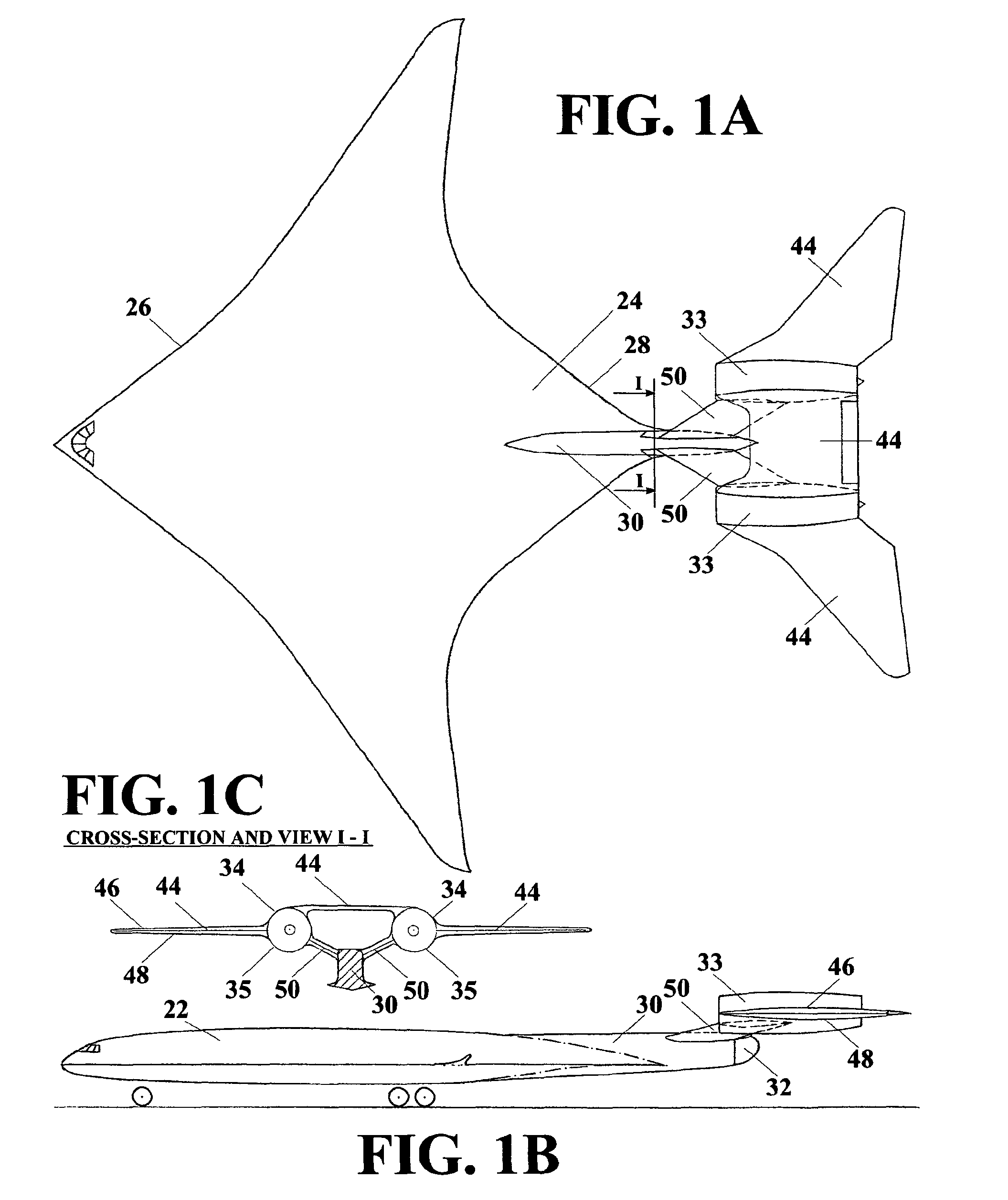
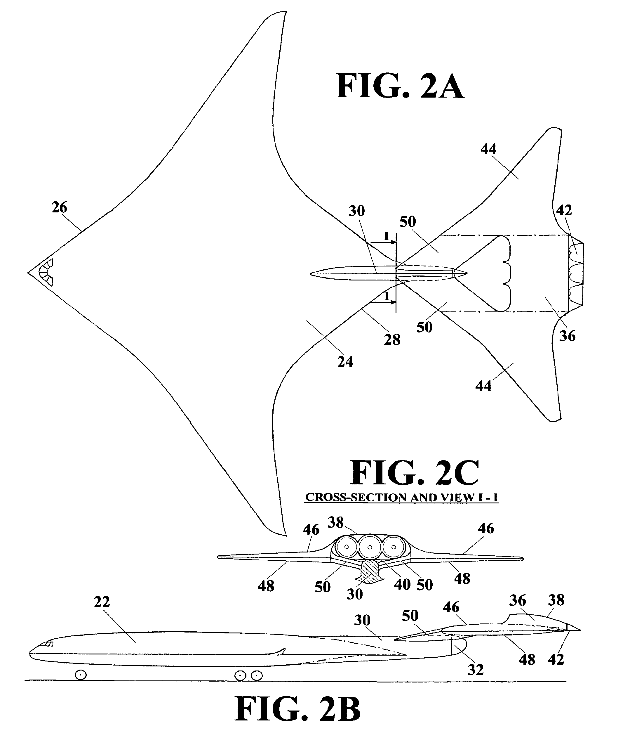
[0042]FIG. 1 shows a Longitudinal Flying Wing jet aircraft that is powered by two lateral jet engines. The Longitudinal Flying Wing aircraft as shown in FIG. I is composed of front wing (22), two lateral jet engines with rigid aerodynamic covers thereof (33), rear wings (44), and V-tail (50). Front wing (22) is the largest aerodynamic body of the Longitudinal Flying Wing aircraft that is providing for the highest amount of aerodynamic lift, while carrying the largest amount of fuel. Front wing central section (24), which is having the longest chord is housing bulky payload, cockpit, and landing gears. Fronts wing central section (24) is having vertical aft reinforcement (30) that is aerodynamically shaped in airflow direction and extending far behind mean geometric chord of front wing (22). V-tail (50) which carries rear wings (44), jet engines, and jet engine aerodynamic covers (33) is fastened on its bottom to the rear portion of vertical aft reinforcement (30). The airframes of a...


PUM


Abstract

The Longitudinal Flying Wing aircraft idea provides for design of large cargo and passenger aircraft in range from low to high subsonic and transonic speed. Such aircraft would have up to twice lower fuel consumption per unit of payload, higher lift capacity, and a significantly longer range, while having a significantly lower level of noise inside passenger cabin and cockpit relative to classical concept aircraft. This idea is further providing for efficient, reliable, and simple flight controls, hence it may be successfully applied for design of all-size, long range, high-lift-capacity unmanned aircraft throughout the entire range of subsonic speeds.

Description

BACKGROUND OF INVENTION[0001]This invention relates to a new aerodynamic concept of aircraft based on flying wing idea that had emerged around 80 years ago, which anticipates the elimination of all surfaces that are not generating lift in order to minimize wetted area with a simultaneous increase of airlifting area, thus increasing the lift capacity, as well as minimizing aerodynamic drag and fuel consumption of aircraft.[0002]For the past 80 years, we have seen a large number of different ideas as to how to practically realize this idea in the most effective way. Some of the relevant ideas may be found among sited references. Unfortunately, no such idea has risen up to a sufficiently high level to meet safety requirements and official regulations for civil air transportation with competitive aerodynamic efficiencies relative to classical concept aircraft at high subsonic speeds. There have been two main obstacles that resulted with such outcome including difficulties related to att...

Claims


Application Information

Patent Timeline
Patent Type & Authority Patents(United States)
IPC IPC(8): B64C1/00
CPCB64C3/10B64C5/02B64C39/08B64D27/10B64D27/16B64C2039/105Y02T50/12Y02T50/44Y02T50/10Y02T50/40
Inventor DIZDAREVIC, FARUKDIZDAREVIC, MITHAD
Owner DIZDAREVIC FARUK
Why Eureka
Try Eureka