
Apparatus and method for frequency generation

a frequency generator and frequency generation technology, applied in the direction of pulse generator, pulse generator, electric pulse generator circuit, etc., can solve the problems of limited frequency range of a single oscillator obtained through capacitance-varying techniques, ic therefore presents certain design difficulties, and substantial inductor-to-inductor coupling is difficult to avoid, so as to prolong the tunable range of the other oscillator and suppress undesirable oscillation modes.

Active Publication Date: 2011-11-15
QUALCOMM INC
View PDF5 Cites 24 Cited by
  • Summary
  • Abstract
  • Description
  • Claims
  • Application Information

AI Technical Summary

Benefits of technology

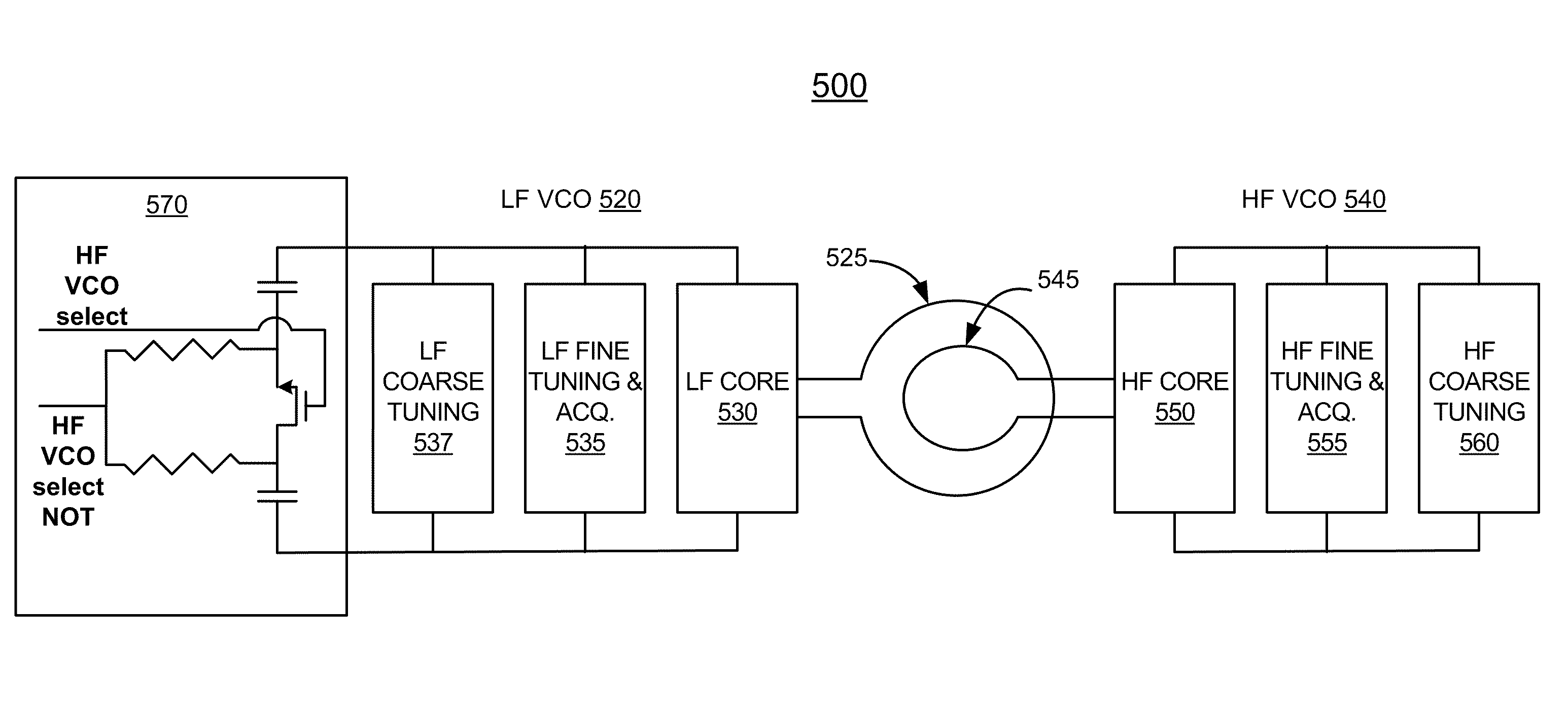
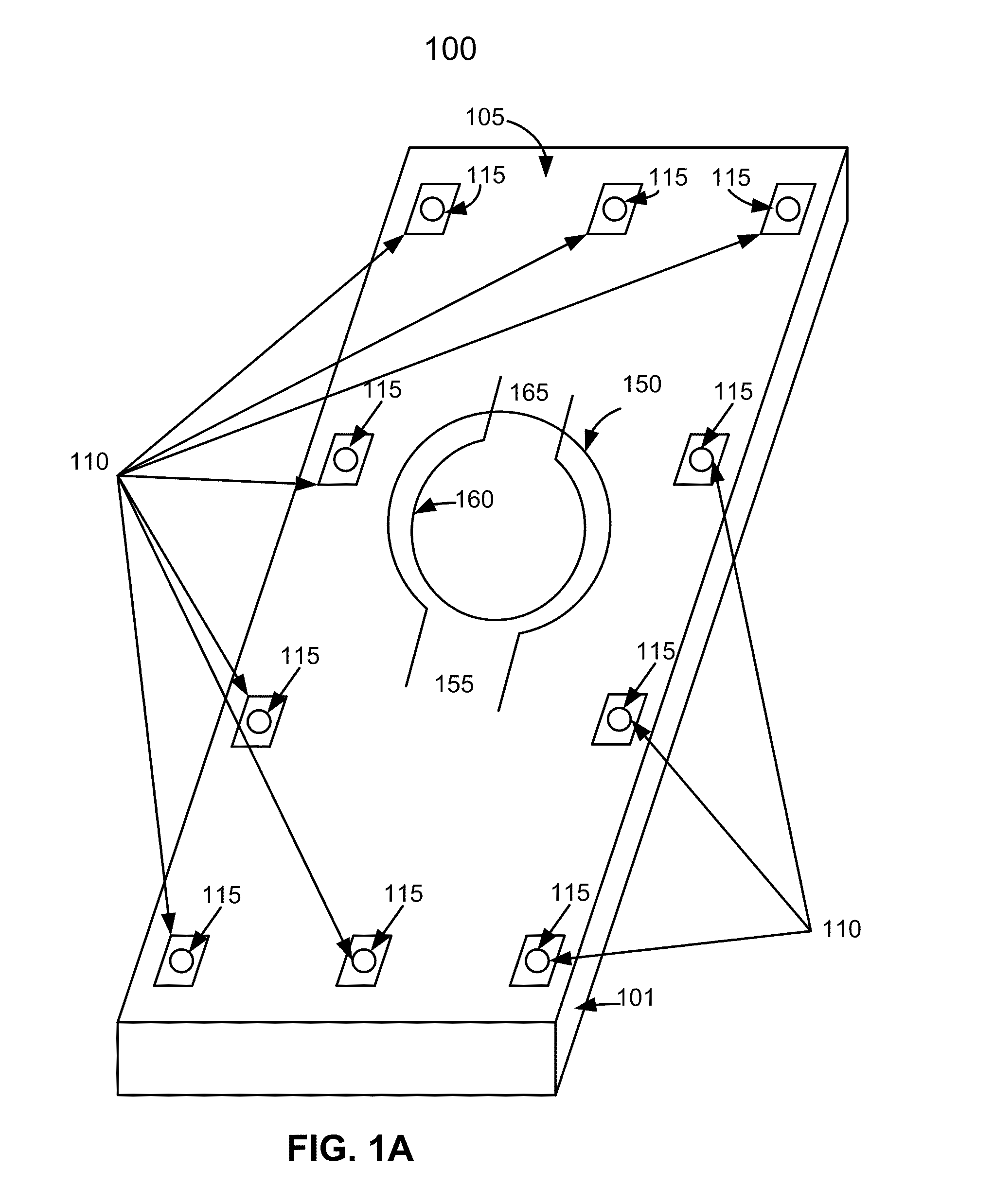
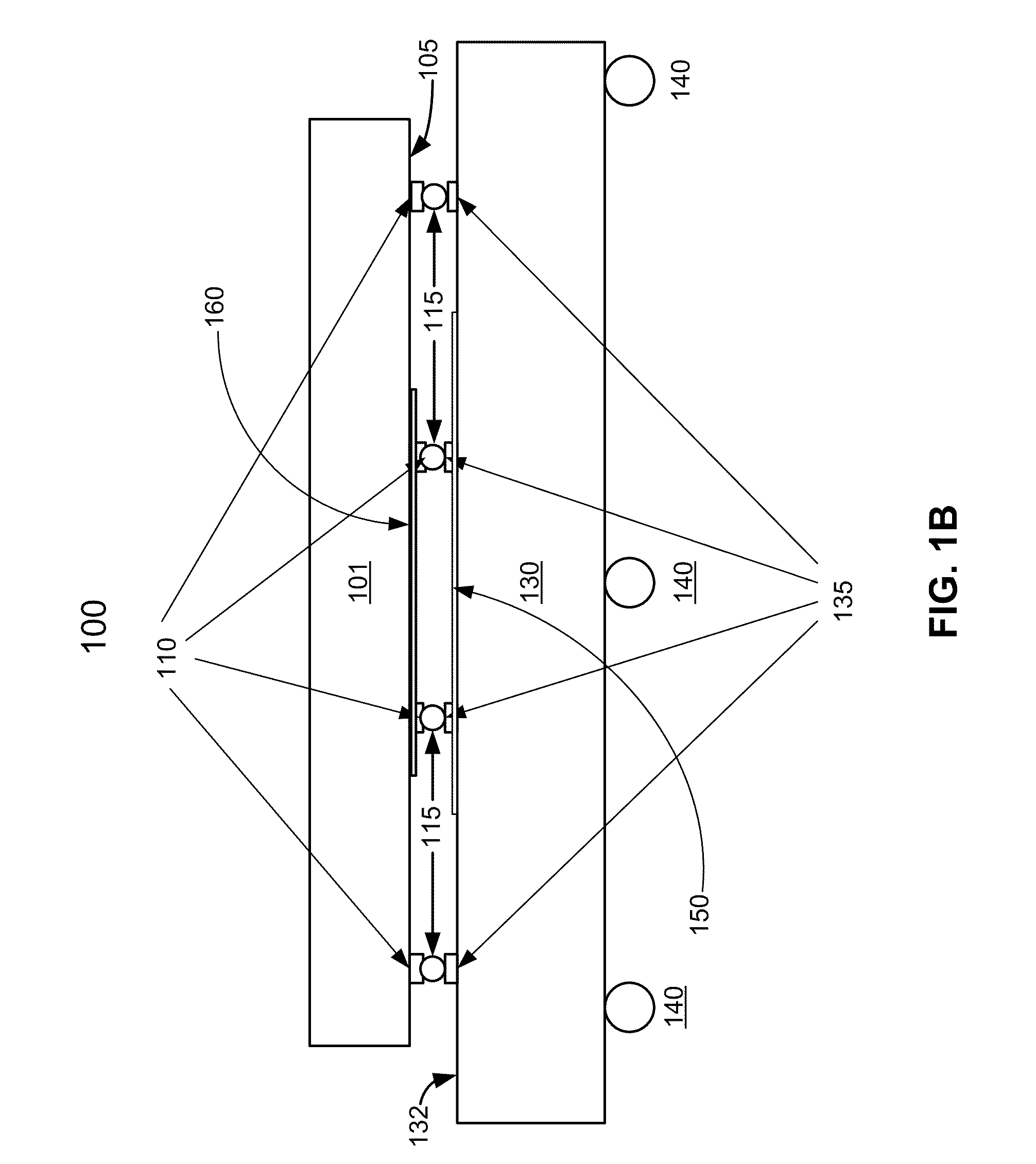
Embodiments disclosed herein may address one or more of the above stated needs by locating the inductor of the first oscillator on the die of a flip chip integrated circuit (IC), and locating the inductor of the second oscillator on the package of the IC. Varying the capacitance in the LC tank of one of the oscillators may extend the tunable range of the other oscillator within the same package, by changing the oscillation mode. Controlling the capacitance and / or the quality factor (Q) of the LC tank of one of the oscillators in a certain way may suppress undesirable oscillation modes of the other oscillator where the inductors of the LC tanks of the two oscillators are loosely coupled.
In an embodiment, an electronic device includes a first oscillator with a first LC tank. The first LC tank includes a first inductor. The electronic device also includes a second oscillator with a second LC tank. The second LC tank has a second inductor. The second inductor is magnetically loosely coupled to the first inductor. The electronic device further includes a coarse tuning circuit for coarse tuning the second oscillator by selectively switching capacitors from a capacitor bank into the second LC tank. The coarse tuning circuit is configured to switch all capacitors of the bank into the second LC tank when the first oscillator is operating and the second oscillator is not operating in order to suppress tendency of the first oscillator to oscillate in an undesirable mode.
In an embodiment, an electronic device includes a first oscillator with a first LC tank. The first LC tank has a first inductor. The electronic device also includes a second oscillator with a second LC tank. The second LC tank has a second inductor. The second inductor is magnetically loosely coupled to the first inductor. The electronic device further includes a first quality factor reducing circuit coupled to the first LC tank. The first quality factor reducing circuit is configured to reduce quality factor of the first LC tank when the second oscillator is operating and the first oscillator is not operating, in order to suppress tendency of the second oscillator to oscillate in an undesirable mode.
In an embodiment, an electronic device has a first oscillator and a second oscillator. The first oscillator has a first LC tank with a first inductor. The second oscillator has a second LC tank with a second inductor. The second inductor is magnetically loosely coupled to the first inductor. The electronic device also includes a means for reducing quality factor of the first circuit when the second oscillator is operating and the first oscillator is not operating in order to suppress tendency of the second oscillator to oscillate in an undesirable mode.
In an embodiment, a method of operating a frequency generator that has a first oscillator and a second oscillator includes activating the first oscillator while not activating the second oscillator, and a step for reducing quality factor of a tank circuit of the second oscillator to reduce tendency of the first oscillator to oscillate in an undesirable mode.

Problems solved by technology

For a variety of reasons, the frequency range of a single oscillator obtained through these capacitance-varying techniques is limited.
Locating two or more LC oscillators on the same IC therefore presents certain design difficulties.
Given the physical proximity of the inductors located on the same IC, however, can make substantial inductor-to-inductor coupling difficult to avoid.
Such coupling may result in unwanted oscillation modes of a particular oscillator, in addition to the desired oscillation mode resulting from the resonance of the LC tank of the oscillator.

Method used


Image

  • Apparatus and method for frequency generation
  • Apparatus and method for frequency generation
  • Apparatus and method for frequency generation

Examples


Embodiment Construction

In this document, the words “embodiment,”“variant,” and similar expressions are used to refer to particular apparatus, process, or article of manufacture, and not necessarily to the same apparatus, process, or article of manufacture. Thus, “one embodiment” (or a similar expression) used in one place or context may refer to a particular apparatus, process, or article of manufacture; the same or a similar expression in a different place may refer to a different apparatus, process, or article of manufacture. The expression “alternative embodiment” and similar phrases may be used to indicate one of a number of different possible embodiments. The number of possible embodiments is not necessarily limited to two or any other quantity.

The word “exemplary” may be used herein to mean “serving as an example, instance, or illustration.” Any embodiment or variant described herein as “exemplary” is not necessarily to be construed as preferred or advantageous over other embodiments or variants. Al...


PUM


Abstract

A wideband frequency generator has two or more oscillators for different frequency bands, disposed on the same die within a flip chip package. Coupling between inductors of the two oscillators is reduced by placing one inductor on the die and the other inductor on the package, separating the inductors by a solder bump diameter. The loosely coupled inductors allow manipulation of the LC tank circuit of one of the oscillators to increase the bandwidth of the other oscillator, and vice versa. Preventing undesirable mode of oscillation in one of the oscillators may be achieved by loading the LC tank circuit of the other oscillator with a large capacitance, such as the entire capacitance of the coarse tuning bank of the other oscillator. Preventing the undesirable mode may also be achieved by decreasing the quality factor of the other oscillator's LC tank and thereby increasing the losses in the tank circuit.

Description

BACKGROUND1. FieldApparatus and methods described in this document relate to frequency generators and methods for frequency generation. More specifically, the apparatus and methods relate to frequency generation using multiple oscillators.2. BackgroundTunable frequency generators are used in many different electronic devices. Wireless communication devices, for example, use frequency generators for upconversion of transmitted signals to intermediate and RF frequencies, and for downconversion of received signals to intermediate and baseband frequencies. Because operating frequencies vary, the generators' frequencies need to be tunable.Frequency coverage required for multiple communication standards and multiple bands typically necessitates wide tuning range oscillators, such as voltage controlled oscillators (VCOs) and digitally controlled oscillators (DCOs). The extent of an oscillator's tuning range is one important performance parameter. It is often desirable to increase the tunin...

Claims


Application Information

Patent Timeline
IPC IPC(8): H03B1/00H03B5/12H03K3/354
CPCH01L23/645H03B21/00H01L23/49816H01L2924/19015H01L2924/15311H01L2224/16225H01L2924/3011H01L2224/05573H01L2224/05568H01L2924/00014H01L2224/0554H01L2224/06135H01L2224/05599H01L2224/0555H01L2224/0556H01L23/64H01L23/498H03B1/02
Inventor RANGARAJAN, RAJAGOPALANMISHRA, CHINMAYABHAGAT, MAULINJIN, ZHANG
Owner QUALCOMM INC
Learn More