
Magnetic core plasmon antenna with recessed plasmon layer

a plasmon layer and magnetic core technology, applied in the direction of perpendicular magnetisation head, record information storage, instruments, etc., can solve the problem of not being able to achieve the most desired condition for tamr writing, the objective of correctly aligning the optical heating profile with the magnetic field profile is not adequately addressed, and the alignment is difficult to achiev

Active Publication Date: 2011-11-15
HEADWAY TECH INC
View PDF7 Cites 25 Cited by
  • Summary
  • Abstract
  • Description
  • Claims
  • Application Information

AI Technical Summary

Benefits of technology

[0010]One objective of the present invention is to provide a TAMR head design wherein the spacing between the magnetic field profile and heating profile is reduced at the magnetic medium without degrading the efficiency of the plasmon mode.
[0011]A second objective of the present invention is to provide a method of manufacturing a TAMR head design according to the first objective that is readily accomplished with existing tools and materials and has flexibility in terms of enabling various plasmon generator layer shapes.
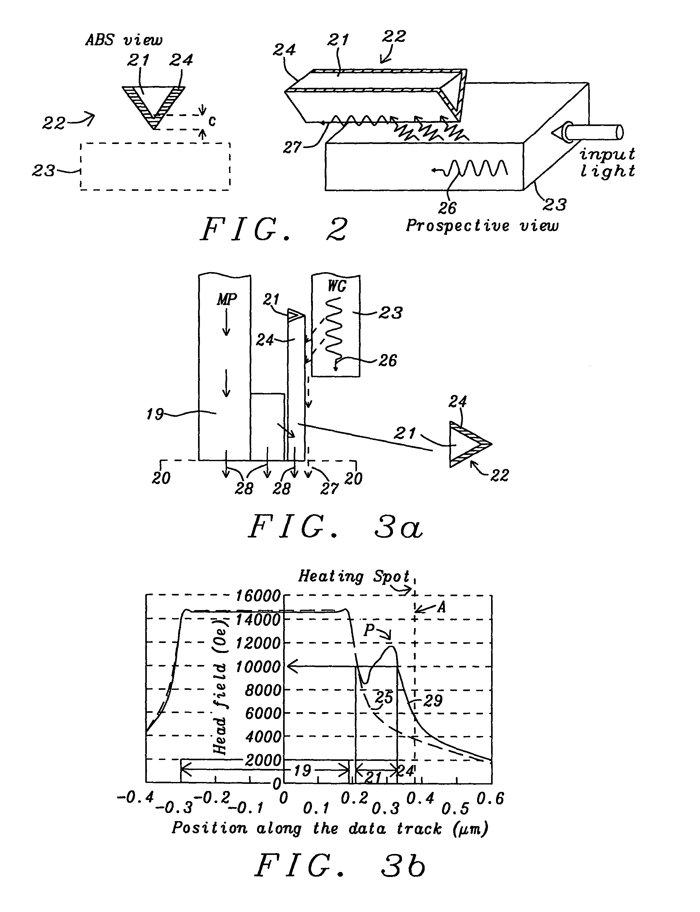
[0012]These objectives are achieved in various embodiments of the present invention wherein a TAMR write head comprises a main pole that has a magnetic core antenna (MCA) overcoated on two converging sides with a plasmon generator (PG) layer. The MCA is formed adjacent to a portion of either a trailing side or leading side of the main pole. Preferably, the MCA has a triangular design having two sides made of a PG layer comprising a highly conductive, non-magnetic metal that intersect at a vertex which is substantially a straight edge. The third side of the triangular shape and a core formed between the two PG layer sides is made of a magnetic material. In one embodiment, the third side and core may be adjoined to a side of the main pole layer and are generally made of the same magnetic material as in the main pole. Alternatively, there may be a non-magnetic separation layer formed between the third side of the MCA and the main pole. In the preferred embodiments, the vertex is formed essentially perpendicular to the ABS and faces a waveguide that is recessed a certain distance from the ABS to reduce optical leakage. Alternatively, the waveguide may have an end at the ABS. The vertex extends in a lengthwise direction parallel to the lengthwise directions of the MCA and waveguide towards the back end of the TAMR head. PG layers are covered with a dielectric layer that separates the MCA from the waveguide and has a low index of refraction to enable efficient optical radiation transfer from the waveguide to the MCA.
[0013]A key feature of the present invention is that an end of the PG layer facing the ABS is recessed a certain distance from the ABS. In effect, the magnetic core of the MCA extends to the ABS and the magnetic layer formed between the PG layer end and ABS may have the same shape as the MCA from an ABS view. In other words, a portion of the magnetic layer follows the “V” shape of the PG layer from an end of the PG layer to the ABS. In another embodiment, the magnetic layer between the PG layer end and ABS is part of a trapezoidal shaped pole tip region from an ABS view wherein the trailing edge of the pole tip is formed substantially coplanar with the MCA vertex.
[0014]According to one embodiment, the end of the PG layer facing the ABS may be formed in a plane that is parallel to the ABS. In another embodiment, the PG layer end facing the ABS is tapered such that the vertex has a greater length in a direction perpendicular to the ABS than the other two PG edges of the triangular shaped MCA that terminate at the magnetic third side. Thus, the tapered PG layer shape allows for a gradual magnetic flux concentration into the magnetic layer between the PG layers and ABS, and the magnetic layer transmits the plasmon mode into the magnetic medium while delivering a head field at the same location to provide improved overlay of the thermal gradient on the magnetic field gradient.

Problems solved by technology

However, in current TAMR configurations, alignment has been difficult to achieve and there is need for improvement in order to compete with other forms of magnetic recording such as microwave assisting magnetic recording (MAMR).
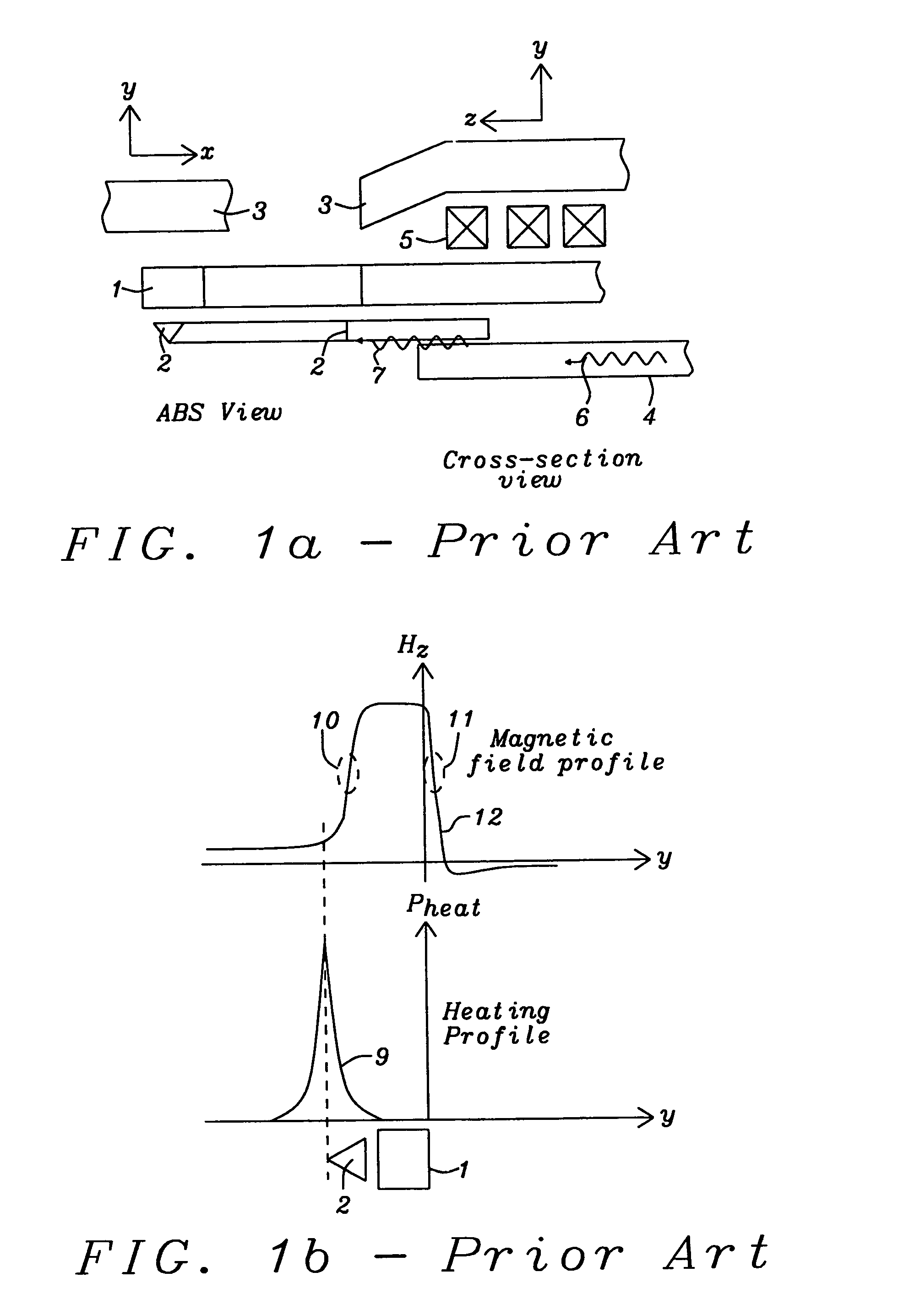
In the prior art, the objective of correctly aligning the optical heating profile with the magnetic field profile has not been adequately addressed.
Although this configuration can achieve writing when sufficient heating is applied, it is not the most desired condition for TAMR writing.
Due to structural waveguide limitations such as thickness and configuration, and the choice of antenna design, a highly effective alignment of magnetic and thermal gradients has not been fabricated yet in TAMR technology.
In addition to the issue of down-track mis-alignment as mentioned above, cross-track alignment is also affected by the overlay of the antenna heating spot on the highest head field.

Method used


Image

  • Magnetic core plasmon antenna with recessed plasmon layer
  • Magnetic core plasmon antenna with recessed plasmon layer
  • Magnetic core plasmon antenna with recessed plasmon layer

Examples


first embodiment

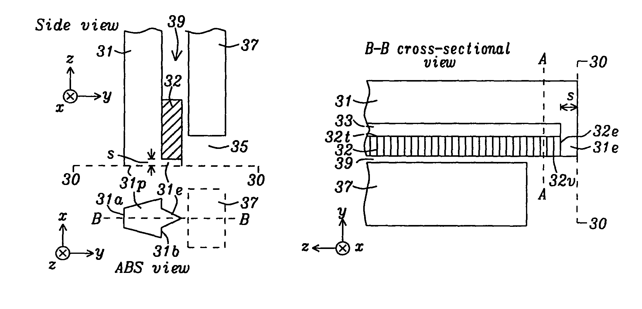
[0037]Referring to FIG. 5a, a TAMR head including a MCA configuration with a recessed PG layer 32 is shown from a side view (top) and an ABS view (bottom) according to the present invention. In the drawings depicted hereinafter, the x-axis refers to the cross-track direction, the y-axis is the down-track direction, and the z-axis arrow points toward a back end of the device. Main pole 31 is comprised of a magnetic material and has an end 31p called a pole tip along the ABS 30-30. Write pole 31p has an edge 31b on a first main pole side that is adjacent to an MCA which includes a PG layer 32 and a magnetic core (not shown in the side view). There is also an edge 31a on a side of the main pole opposite the first side. The PG layer 32 is a non-magnetic material comprised of one or more of Au, Ag, Cu, Al, Ti, Ta, and Ge with a thickness from about 10 to 100 nm. In this embodiment, the MCA has a triangular shape from an ABS view and the PG layer 32 is recessed by a distance “s” of 5 to 1...

second embodiment

[0046]Referring to FIG. 11, an alternative version of the second embodiment is depicted. All components previously described with respect to FIGS. 6a-6b are retained in FIG. 11 except the end 32e of PG layer 32 is replaced with a sloped side 32s that connects a top edge 32t to vertex 32v. Instead of having top edge 32t and vertex 32v recessed essentially an equal distance from ABS 30-30 in FIG. 6b, top edge 32t is recessed a greater distance from the ABS than vertex 32v in the B-B cross-sectional view (FIG. 11). From an ABS view, magnetic layer 33e continues the triangular shape of the MCA from side 32s to the ABS and transmits the plasmon mode from the PG layer 32 to the ABS while simultaneously transmitting magnetic flux from main pole 31 and magnetic core 33 to the ABS 30-30 and magnetic medium (not shown).

[0047]Referring to FIG. 12, a third embodiment of the present invention is shown that represents a modification of the first embodiment depicted in FIG. 10. In particular, a ma...

fifth embodiment

[0049]Referring to FIG. 14, the present invention is depicted and represents a modification of the TAMR structure shown in FIG. 10. All components previously described with respect to FIG. 10 are retained in FIG. 14 except the shape of the magnetic layer 31e is changed from an ABS view. In particular, the triangular shape of the magnetic layer is replaced by a trapezoid shape that is larger than the triangular MCA shape. A first side of the magnetic layer 31e interfaces with a side of the main pole 31 that includes edge 31b and is formed in a first plane (not shown) that extends in the z-axis direction from the ABS and includes a side of the PG layer 32 opposite vertex 32v. The first side has a width in a cross-track direction that is essentially the same as that of edge 31b. A side 31c of the magnetic layer 31e opposite edge 31b is formed along a second plane which is parallel to the first plane and includes vertex 32v. Side 31c preferably has a greater width along the cross-track ...


PUM


Abstract

Various embodiments of a TAMR head having a magnetic core antenna (MCA) with a recessed plasmon layer are disclosed. An end of the plasmon layer is separated from the ABS by a magnetic layer that transmits the plasmon mode from the plasmon layer and transmits magnetic flux from an adjacent main pole layer. Both of the MCA and magnetic layer may have a triangular shape from an ABS view. There may be a non-magnetic separation layer between the MCA magnetic core and the main pole. Furthermore, a magnetic shield may be included with a side at the ABS, a side facing an end of a waveguide that transmits electromagnetic radiation to the MCA, and a side facing an edge of the plasmon layer. The recessed plasmon layer allows an improved overlay of the thermal heating spot on the magnetic field gradient at the magnetic medium that provides better TAMR performance.

Description

RELATED PATENT APPLICATIONS[0001]This application is related to the following: Ser. No. 12 / 456,290, filing date Jun. 15, 2009; and Ser. No. 12 / 802,096, filing date May 28, 2010; both assigned to a common assignee and herein incorporated by reference in their entirety.FIELD OF THE INVENTION[0002]The invention relates to magnetic read / write heads based on thermally assisted magnetic recording (TAMR) and in particular to a structure in which a magnetic core antenna (MCA) has a plasmon generator layer that is recessed from an air bearing surface (ABS) to minimize the spacing between the magnetic field peak and heating profile peak at the magnetic medium and thereby improves writing efficiency and increases data density.BACKGROUND OF THE INVENTION[0003]TAMR is expected to be one of the future generations of magnetic recording technologies that will enable recording at ˜1-10 Tb / in2 data densities. TAMR involves raising the temperature of a small region of the magnetic medium to near its C...

Claims


Application Information

Patent Timeline
IPC IPC(8): G11B11/00
CPCG11B5/1278G11B5/3116G11B5/314G11B5/6088G11B2005/0021
Inventor ZHOU, YUCHENJIN, XUHUITAKANO, KENICHIDOVEK, MORISMALETZKY, TOBIASSCHRECK, ERHARDSMYTH, JOE
Owner HEADWAY TECH INC
Learn More