Variable geometry turbocharger, vane ring assembly with retaining member

a turbocharger and variable geometry technology, applied in the direction of machines/engines, manufacturing tools, liquid fuel engines, etc., can solve the problems of affecting the performance of the turbocharger, so as to reduce the potential for vanes, maintain efficiency, and cost-effective

Active Publication Date: 2011-11-22
BORGWARNER INC
View PDF6 Cites 26 Cited by
  • Summary
  • Abstract
  • Description
  • Claims
  • Application Information

AI Technical Summary

Benefits of technology

[0024]The exemplary embodiments of the vane ring assembly effectively decouple the assembly of the vane ring from the turbine housing and eliminate the potential for vanes to stick due to relative movement through thermal growth, as is experienced when the lower and upper vane support rings are rigidly affixed to each other and the turbine housing via studs, bolts, and the like. The exemplary embodiments provide a fastening system and method for connecting the vane ring assembly to the turbine housing that negates the effect of thermal growth, or the effects of differential thermal growth, of the housing and / or vane ring assembly while maintaining efficiencies. The exemplary embodiments are cost effective, dependable, and are designed for ease of assembly.

Problems solved by technology

Such conditions have a detrimental effect on the components of the turbocharger.
The design selections, required to satisfy these conditions, often lead to larger than preferred clearances, which, in turn, cause aerodynamic inefficiencies.
This often results in a twisting motion, dependant upon the constraints of the casting geometry.
This relatively simple thermal expansion, combined with the results of the geometric and thermal flux influences, results in complex deformation of the turbine housing across the temperature range.
This displacement of the fastener causes distortion in the vane rings which then causes the vanes and moving components to stick.
If the clearances between components are made greater in order to reduce the propensity of the vanes to stick, the excessive clearances cause a loss of aerodynamic efficiency, which is unacceptable.
The displacement of the fasteners also generates high stress in the fastener, which results often in failure of the fastener.
Unusual wear patterns, due to distortion in the vane ring, also generate unwanted clearances, which further reduce the aerodynamic efficiency.
Tapped holes are a reasonably efficient manufacturing method but are simply not effective when it comes to dimensional accuracy or repeatability.
While it is normal practice to generate acceptable accuracy and repeatability with drilled or reamed holes, the threading activity is fraught with problems.
Due to the integral connection of the housing (1) with the vane table (6), the Fukaya turbocharger suffers from the drawbacks of having to allowing gaps to account for thermal growth.
Such gaps reduce the performance of the turbocharger.
Such materials can be costly and difficult to work with.
The Arnold device also suffers from the drawback of radial thermal expansion of the turbine housing imparting undue stress and / or movable components “sticking” due to the use of the vane post connection in the housing.

Method used


Image

  • Variable geometry turbocharger, vane ring assembly with retaining member
  • Variable geometry turbocharger, vane ring assembly with retaining member
  • Variable geometry turbocharger, vane ring assembly with retaining member

Examples


Embodiment Construction

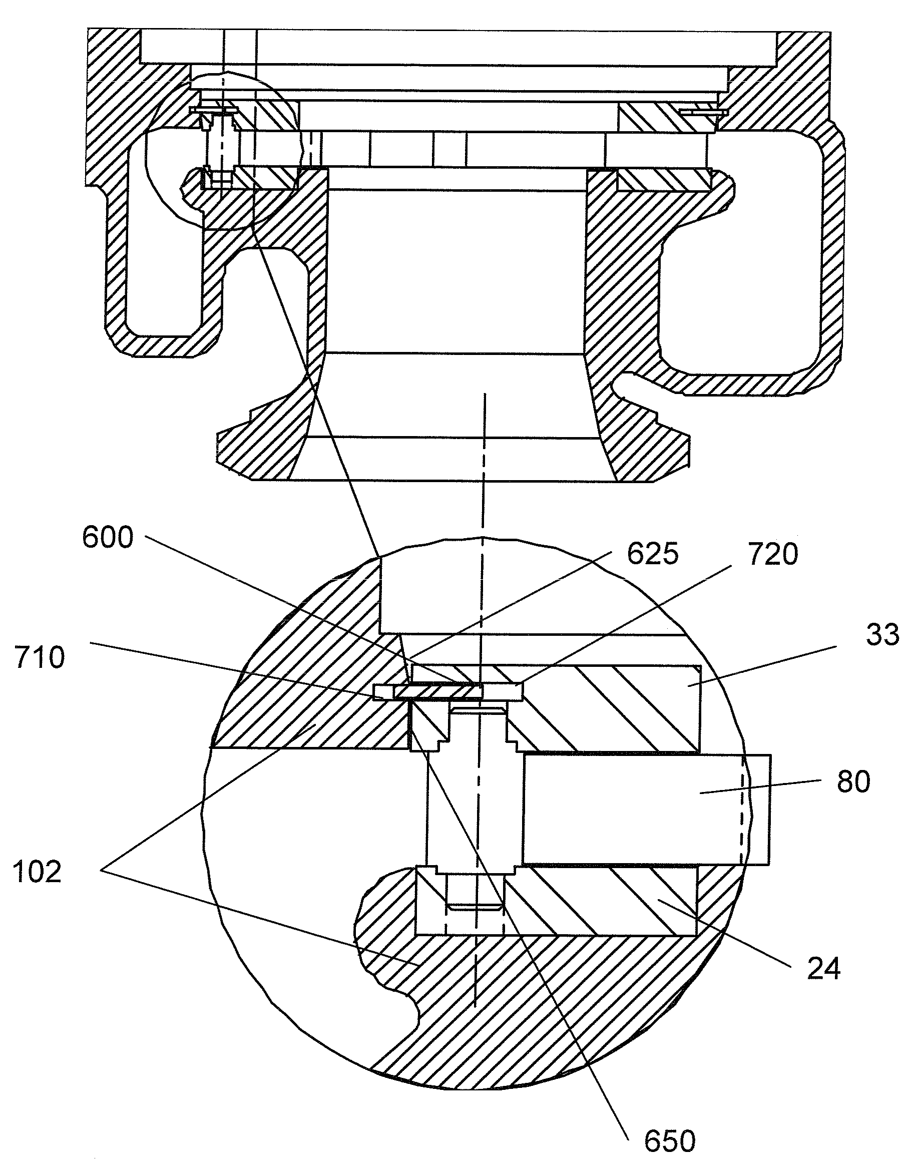
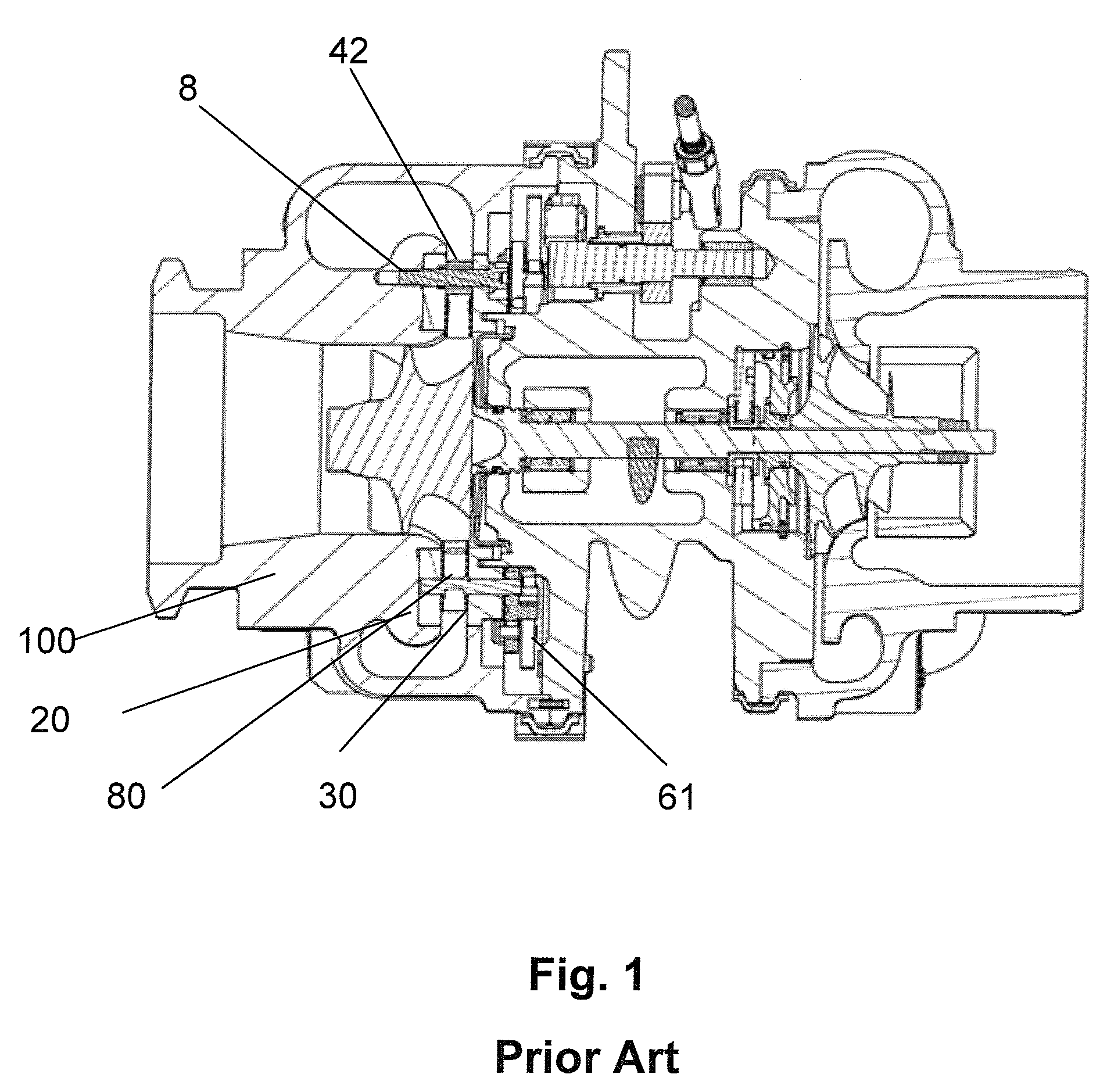
[0050]A turbocharger has five major component groups: A compressor housing; a turbine housing; a center section, incorporating the bearing system and providing support and location for the turbine housing and compressor housing; and the compressor and turbine wheels. Within the turbine housing assembly there exists the upper vane ring (30) supporting a plurality of VTG vanes (80) which are sandwiched between the upper vane ring (30) and the lower vane ring (20) such that a spacer (49, 50, 59) locates the vanes rings in the axial relationship with each other with the distance between each vane ring set by the combination of: in the case of a stepped spacer, the distance between the steps on the spacer (50) and the counterbores in each of the upper and lower vane rings. In the case of a non-stepped spacer (49) the distance between end-faces of the spacers and the faces of the lower and upper vane rings.

[0051]To control the width of the vane space, which is the distance of the lower va...


PUM

PropertyMeasurementUnit
temperatureaaaaaaaaaa
outer diameteraaaaaaaaaa

Abstract

A vane ring assembly which includes a lower vane ring (23), an upper vane ring (31), one or more guide vanes (80) positioned at least partially between the vane rings, and a plurality of spacers (49, 50 or 59) positioned between the lower and upper vane rings (23, 31) for maintaining a distance between the lower and upper vane rings, the vane ring assembly being retained in a turbine housing (102) by a retaining ring (400) which is located in a groove (510) in the turbine housing.

Description

FIELD OF THE INVENTION[0001]This invention is directed to a turbocharging system for an internal combustion engine and more particularly to a design of a VTG system for allowing simplified assembly of components of the turbocharger as well as reduced deformation due to differential thermal expansion.BACKGROUND OF THE INVENTION[0002]Turbochargers are a type of forced induction system. They deliver compressed air to the engine intake, allowing more fuel to be combusted, thus boosting the engine's horsepower without significantly increasing engine weight. This can allow for the use of a smaller turbocharged engine, replacing a normally aspirated engine of a larger physical size, thus reducing the mass and aerodynamic frontal area of the vehicle. Turbochargers use the exhaust flow from the engine to drive a turbine, which in turn, drives the air compressor. At startup, the turbocharger may be at temperatures well below 0° C. Since the turbine turns at extremely high speed, in the range ...

Claims


Application Information

Patent Timeline
Patent Type & Authority Patents(United States)
IPC IPC(8): F02D23/00
CPCB23P19/084F04D29/462Y10T29/49245
Inventor HALL, RICHARD DWAYNE
Owner BORGWARNER INC
Why Eureka
Try Eureka