Heat exchanger with integrated bypass valve

a heat exchanger and bypass valve technology, applied in the direction of indirect heat exchangers, gearing details, light and heating apparatus, etc., can solve the problems of additional manufacturing costs, constructive efforts, and additional interfaces, and achieve the effect of small pressure drop, small and compact design, and improved heat exchanger efficiency

Inactive Publication Date: 2011-11-29
ZF FRIEDRICHSHAFEN AG
View PDF18 Cites 1 Cited by
  • Summary
  • Abstract
  • Description
  • Claims
  • Application Information

AI Technical Summary

Benefits of technology

[0014]By advantageously configuring and arranging the ducts for the transmission lubricant, the transmission housing directly forms the housing for the heat exchanger. This results in the forced conduction of the entire transmission lubricant across the heat exchanger. This improves the efficiency of the heat exchanger, achieving a smaller and more compact design. By way of short ducts and a large flow cross-section, which may be constituted by a systematic integration in the transmission housing, a very small pressure drop is obtained. Only simple and economic adapter parts are required for oil conduction, sealing and attachment. Even with regard to the connection of the coolant, this guarantees a simple and reliable system without additional sealing elements.
[0015]Despite the high level of integration the retrofitting and dismantling are easily accomplished without having to disassemble the entire transmission. The simple design and small number of interfaces result in low manufacturing costs. At the same time, very good protection of the heat exchanger from damage or other mechanical effects is achieved.
[0019]The bypass valve arranged at the heat exchanger is automatically mounted together with the heat exchanger in the transmission housing, guaranteeing high system reliability. The bypass function may be accomplished with a very compact design by arranging the bypass valve at the heat exchanger and integrating the bypass ducts in the transmission housing. Compared to a constructively separated bypass function, corresponding interfaces may be reduced by means of the integrated bypass function, thus solving the problem of leaks. By skillfully arranging the bypass ducts in the transmission housing, the constructive effort for the bypass function is minimal and therefore cost-effective.

Problems solved by technology

In modern vehicle transmissions subject to high loads, the transmission lubricant has to be cooled to temperatures that are uncritical for the system.
The disadvantages of the prior art are, among other things, that additional interfaces are necessary for the constructively separated bypass valve which have to be sealed against leaks.
Moreover, a bypass which is constructively separated from the heat exchanger and the power train to be cooled or warmed up requires appropriate constructive efforts and consequently also additional manufacturing costs.

Method used


Image

  • Heat exchanger with integrated bypass valve
  • Heat exchanger with integrated bypass valve
  • Heat exchanger with integrated bypass valve

Examples


Embodiment Construction

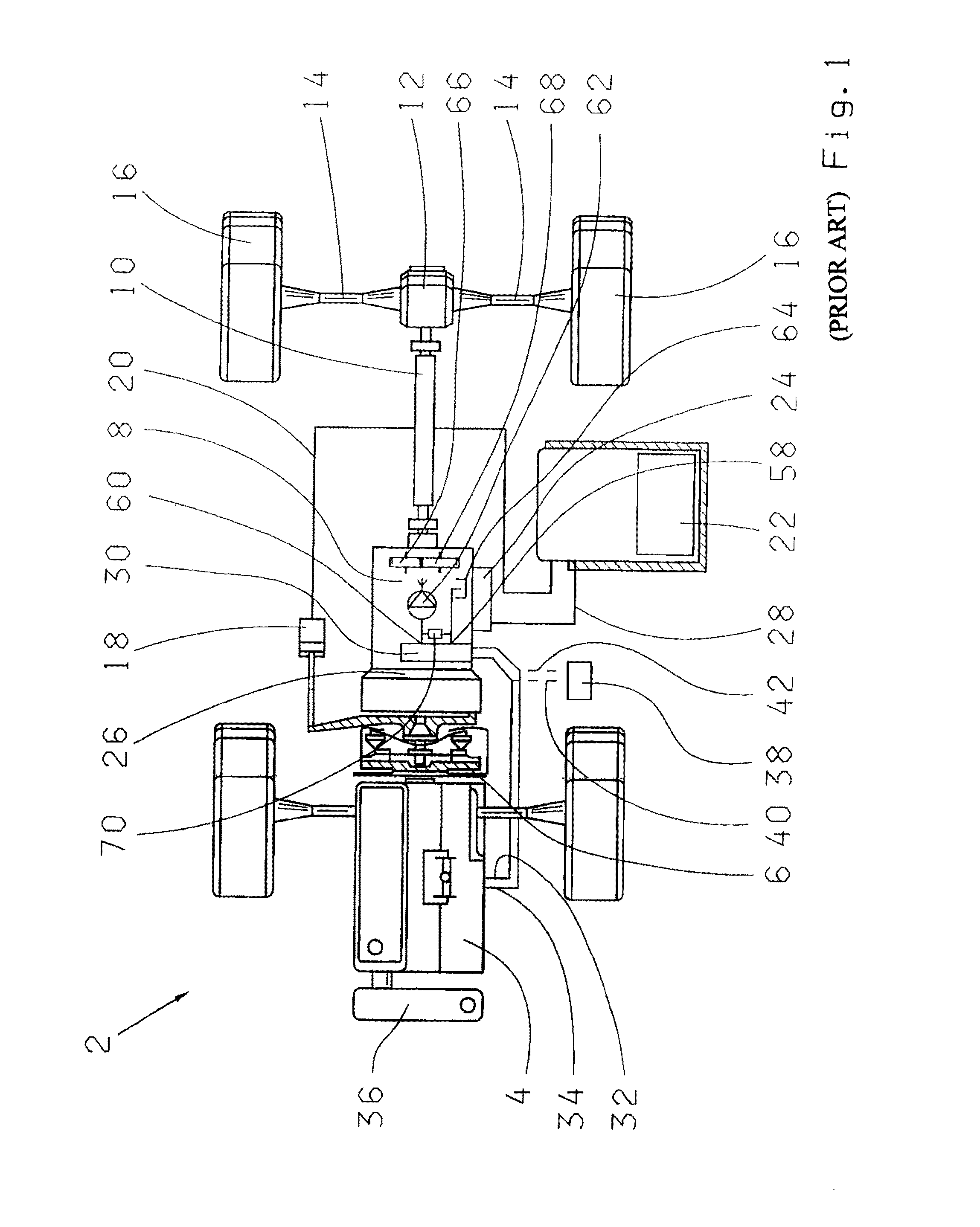
[0025]FIG. 1 shows a schematic illustration of a vehicle 2 having a drive motor 4, which acts upon a transmission 8 by means of a friction clutch 6. The transmission 8 is connected, via an output shaft 10, to a differential 12 which drives a vehicle wheel 16 via a half axle 14. The friction clutch 6 is actuated by an actuator 18, which is connected to a control unit 22 via a signal line 20. The transmission 8 is actuated by a transmission controller 24 which is arranged on the housing 26 of the transmission 8 and is connected to the control unit 22 via a line 28. A heat exchanger 30, which is connected to the motor 4 and the coolant via two coolant lines 32 and 34, is installed in the housing 26. The warmed-up coolant is cooled down in a vehicle cooling unit 36. A cooling unit 38 which is mounted on the vehicle 2 may alternatively be connected to the heat exchanger 30, via the coolant lines 40 and 42, in which the coolant of the heat exchanger 30 is then cooled down. The heat exchan...


PUM


Abstract

A transmission (8) having a transmission housing (26) having a region in which gear wheels (66, 68) rotate and a heat exchanger (30) which absorbs the heat generated in the transmission (8). This heat is transferred to a transmission lubricant and released to a coolant to transport the heat away from the transmission (8). A recess (56) is provided, in the transmission housing (26) outside of the region in which the gearwheels (66, 68) rotate, through which transmission lubricant flows and in which the heat exchanger (30) is arranged. The heat exchanger (30) has a bypass valve (48) which enables the heat exchanger (30) to be bypassed starting at a predefined low or excess pressure.

Description

[0001]This application is a national stage completion of PCT / EP2007 / 055577 Jun. 6, 2007 which claims priority from German Application Serial No. DE 10 2006 030 790.9 filed Jun. 30, 2006.FIELD OF THE INVENTION[0002]The present invention relates to a heat exchanger and a transmission with a heat exchanger.BACKGROUND OF THE INVENTION[0003]In modern vehicle transmissions subject to high loads, the transmission lubricant has to be cooled to temperatures that are uncritical for the system. In particular, in surroundings with high ambient temperatures and for vehicles in which the transmission is encapsulated for noise reduction reasons, cooling devices are accordingly provided in the form of heat exchangers. Heat exchangers are normally used for additional cooling of the transmission lubricant, but may also be used for warming up the transmission lubricant.[0004]The currently known heat exchangers are either oil / air or oil / water heat exchangers and are mounted as additional components at ...

Claims


Application Information

Patent Timeline
Patent Type & Authority Patents(United States)
IPC IPC(8): F16H57/04
CPCF28F27/02F28D7/1638F16H57/0417Y10T74/2189
Inventor FUHRER, GERHARDHORING, GERHARD
Owner ZF FRIEDRICHSHAFEN AG
Why Eureka
Try Eureka