Seamless capsule manufacturing apparatus

a manufacturing apparatus and seamless technology, applied in the direction of manufacturing tools, colloidal chemistry, pharmaceutical product form change, etc., can solve the problems of uneven thickness, vibration other than the vibration applied by the vibration unit, and vibration occurring in the liquid feeding unit, so as to suppress the occurrence of eyes, reduce vibration noise at the time of droplet formation, and enhance product quality

Active Publication Date: 2011-12-06
FREUNT IND
View PDF45 Cites 9 Cited by
  • Summary
  • Abstract
  • Description
  • Claims
  • Application Information

AI Technical Summary

Benefits of technology

[0018]Thus, in the seamless capsule manufacturing apparatus of the present invention that ejects a droplet from a nozzle into hardening liquid to harden at least the surface area of the droplet to thereby manufacture a seamless capsule, since the vibration absorbing means for absorbing vibration generated by the liquid feeding unit in the tube passage is arranged between the liquid feeding unit and nozzle, it is possible to prevent the vibration of the liquid feeding unit from being transmitted to the nozzle. Thus, vibration noise at the time of formation of droplets can be reduced, thereby suppressing occurrence of eyes of the seamless capsule, uneven thickness thereof, or variation in the particle diameter thereof. As a result, product quality can be enhanced and thereby seamless capsules of satisfactory quality can be manufactured stably.

Problems solved by technology

However, in such a seamless capsule manufacturing apparatus, when the liquid feeding pump is activated, vibration occurs in the liquid feeding unit.
When vibration is applied to the nozzle as in the case of the apparatus disclosed in Patent Documents 1 and 3 in a state where the vibration is superposed on the jet flow, it causes a problem in that vibration other than the vibration applied by the vibration unit is added to the jet flow as noise.
When a noise component other than the vibration unit is added to the vibration added to the jet flow, a nonuniform liquid layer may be caused or droplet diameter may become nonuniform, causing problems, such as casing eyes of the seamless capsule, uneven thickness thereof, or variation in the particle diameter thereof.
However, this configuration does not prevent the vibration generated in the pump from being transmitted to the nozzle.
Thus, a problem of the noise vibration cannot be solved.

Method used


Image

  • Seamless capsule manufacturing apparatus
  • Seamless capsule manufacturing apparatus
  • Seamless capsule manufacturing apparatus

Examples


first embodiment

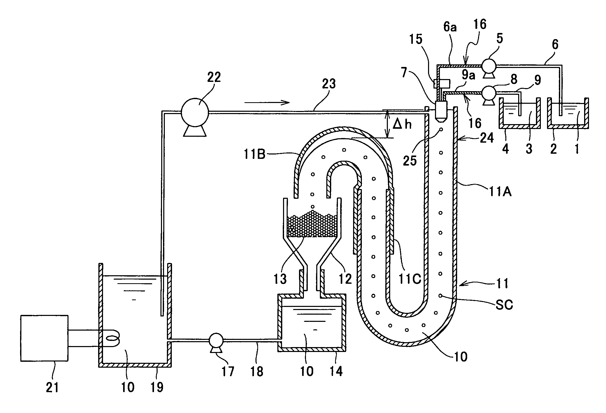
[0085]FIG. 1 is an explanatory view showing a configuration of a seamless capsule manufacturing apparatus according to a first embodiment of the present invention. The seamless capsule manufacturing apparatus shown in FIG. 1 is adapted to manufacture seamless capsules SC by ejecting droplets from a multiple nozzle 7 (hereinafter, abbreviated as “nozzle 7”) into a flow passage tube 11. Core liquid (inner layer liquid) 1 for forming seamless capsules SC is stored in a core liquid tank (liquid tank) 2. Film forming liquid (outer layer liquid) 3 for coating each drop of core liquid 1 is stored in a film forming liquid tank (liquid tank) 4. Core liquid 1 is fed by a pump (liquid feeding unit) 5 to the nozzle 7 under pressure from the core liquid tank 2 by way of a tube passage 6. Film forming liquid 3 is fed to the nozzle 7 under pressure from the film forming liquid tank 4 by way of a tube passage 9 by means of a pump (liquid feeding unit) 8. A heater formed by a nickel-chrome alloy wir...

second embodiment

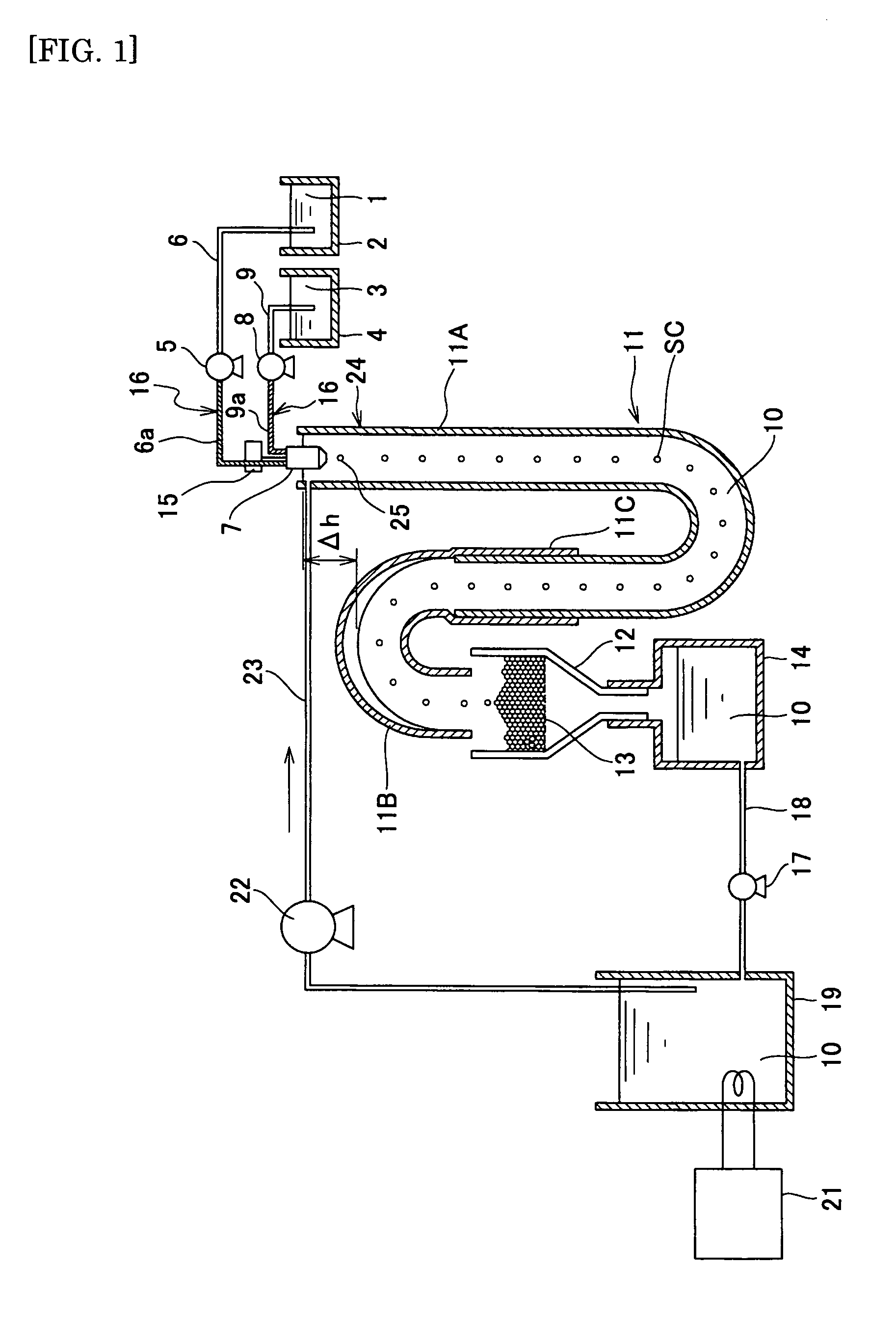
[0093]Next, a seamless capsule manufacturing apparatus according to a second embodiment will be described. In the second embodiment, a vibration absorbing block which is an elastic member is used as a vibration absorbing means. This vibration absorbing block is attached to the outer periphery of the tube passages 6 and 9 to block transmission of the vibration noise. FIG. 2 is an explanatory view showing a configuration of a vibration absorbing block 31 used in the seamless capsule manufacturing apparatus according to the second embodiment. FIG. 2 (a) shows a state before attachment, and FIG. 2 (b) shows a state after attachment. Except for the above, the present embodiment is the same as the first embodiment. Therefore, detailed descriptions of the present embodiment are omitted. Further, the same reference numerals as those in the first embodiment denote the same members or parts as those in the first embodiment, and the descriptions thereof are omitted here.

[0094]As shown in FIG. ...

third embodiment

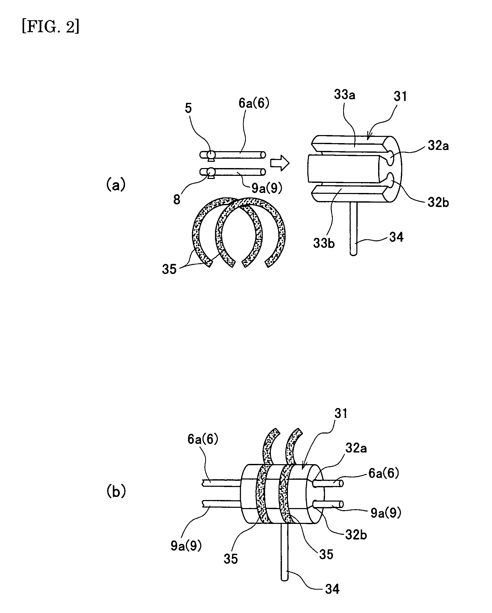
[0097]FIG. 3 is an explanatory view showing a configuration of a vibration absorbing block (vibration absorbing means) 36 used in a seamless capsule manufacturing apparatus according to a third embodiment of the present invention. FIG. 3 (a) shows a state before attachment, and FIG. 3 (b) shows a state after attachment. The vibration absorbing block 36 has substantially the same configuration as that of the vibration absorbing block 31. However, unlike the vibration absorbing block 31, the slits 33a and 33b are not formed in the vibration absorbing block 36. That is, the vibration absorbing block 36 has a configuration in which two tube passage attachment holes 37a and 37b having no slit are formed in a columnar-shaped main body thereof. A block installation bar 38 is fixed to the vibration absorbing block 36. With this configuration, vibration absorbing block 36 is installed at the apparatus main body or the like. Further, a cable tie 39 is wound around the outer periphery of the v...


PUM

PropertyMeasurementUnit
inner diameteraaaaaaaaaa
surface areaaaaaaaaaaa
flexibleaaaaaaaaaa

Abstract

In a seamless capsule manufacturing apparatus that ejects a droplet from a nozzle into hardening liquid to manufacture a seamless capsule SC, tube passages which are synthetic resin tubes are provided as flexible sections between pumps and the nozzle. The vibration caused by the pumps is absorbed in the flexible sections and thus is not transmitted to the nozzle, whereby eyes or the like of the seamless capsule caused by vibration noises can be suppressed. Instead of a synthetic resin tube, a vibration absorbing block formed of an elastic member may be attached to the tube passages. Alternatively, a vibration absorbing unit, which is provided with a pad formed of an elastic member and for holding the tube passages, may be provided.

Description

TECHNICAL FIELD[0001]The present invention relates to a manufacturing technique of a seamless capsule that encapsulates a filler material such as a food product, a health food product, a medicine, a flavor, or a spice, with a capsule shell material such as gelatin or vegetable gelatin.BACKGROUND ART[0002]Conventionally, many seamless capsules used for a medicine or the like are manufactured by a so-called dropping method. The dropping method is carried out by using a multiple nozzle. Thus, in the case of manufacturing a two-layer capsule, a double nozzle having an ejection port for ejecting the capsule filling substance and an ejection port for ejecting the film forming substance respectively arranged at the inside and at the outside is used. The filling substance and the film forming substance are ejected from the tips of the respective nozzles into hardening liquid, and the ejected liquid drops take a spherical form due to the surface tension thereof. Then, the liquid drops are co...

Claims


Application Information

Patent Timeline
Patent Type & Authority Patents(United States)
IPC IPC(8): B01J13/02
CPCA61J3/07B01J13/04A23P1/04A23P10/30
Inventor TAKEI, NARIMICHINAGAO, HIROSHI
Owner FREUNT IND
Why Eureka
Try Eureka