Stepping motor driver

a technology of stepping motor and stepping motor, which is applied in the direction of programme control, dynamo-electric converter control, instruments, etc., can solve the problems of high-impedance output, rotor is likely to lose synchronization, and detection requires a relatively long period of high-impedance output, so as to reduce distortion, stop the determination of rotor, and suppress the distortion of an energization waveform.

Inactive Publication Date: 2011-12-06
PANASONIC CORP
View PDF12 Cites 15 Cited by
  • Summary
  • Abstract
  • Description
  • Claims
  • Application Information

AI Technical Summary

Benefits of technology

[0006]In the present invention, an electromotive force is generated on the coil of a motor with a sinusoidal wave having the same period as an energization period by smoothly rotating a rotor with microstep driving, and an induced power is stably detected by detecting the electromotive force at the zero cross of driving current. The present invention provides a circuit which is aimed at reducing a detection section through detection around the zero cross of current, forming a driving waveform with few distortions, and performing driving with a driving waveform as in an ordinary microstep method. Further, the circuit is aimed at reducing noise, vibrations, and loss of synchronization, and increasing current consumption efficiency in the determination of stop.
[0008]The present invention can suppress the distortions of an energization waveform of a stepping motor and enable the stop determination of a rotor. By reducing distortions, it is possible to reduce vibrations, noise, loss of synchronization, and power consumption which adversely affect stop determination in the prior art.

Problems solved by technology

Further, in order to detect a change of current and voltage of induced power on a coil to be detected in the prior art, sufficient time is necessary for the discharge of applied current and a sequence of repeating detection several times, and an exciting method is limited to full-step driving, half-step driving, and so on.
Although a microstep method is available, detection requires a high-impedance output for a relatively long period.
A high-impedance section deforms a load current waveform and forms a driving waveform for each phase, so that noise and vibrations may occur on a stepping motor and a rotor is likely to lose synchronization.
Moreover, such a method causes large power consumption and low efficiency, so that driving with an ideal microstep waveform is impossible in the determination of stop.

Method used


Image

  • Stepping motor driver
  • Stepping motor driver
  • Stepping motor driver

Examples


first embodiment

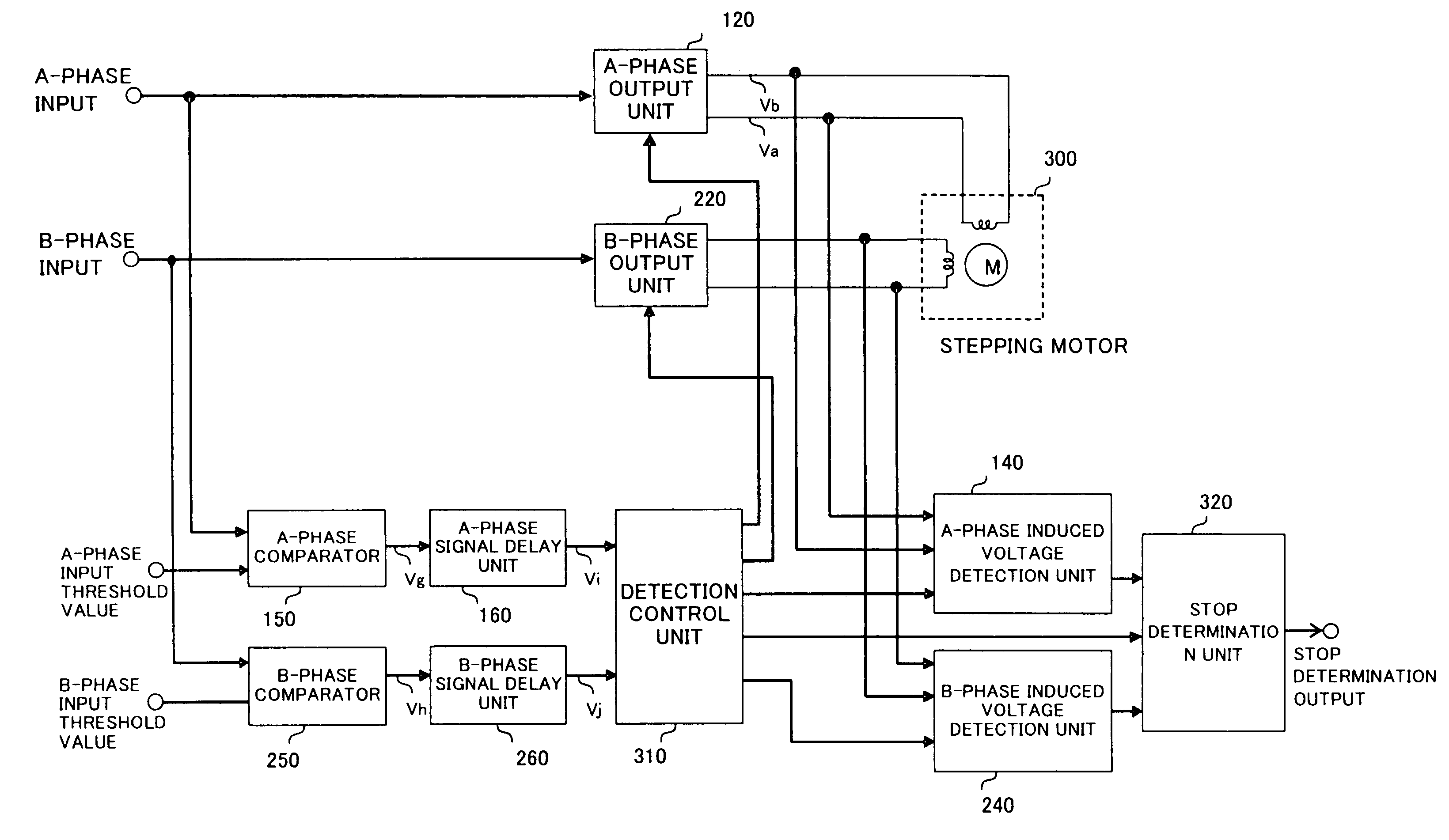
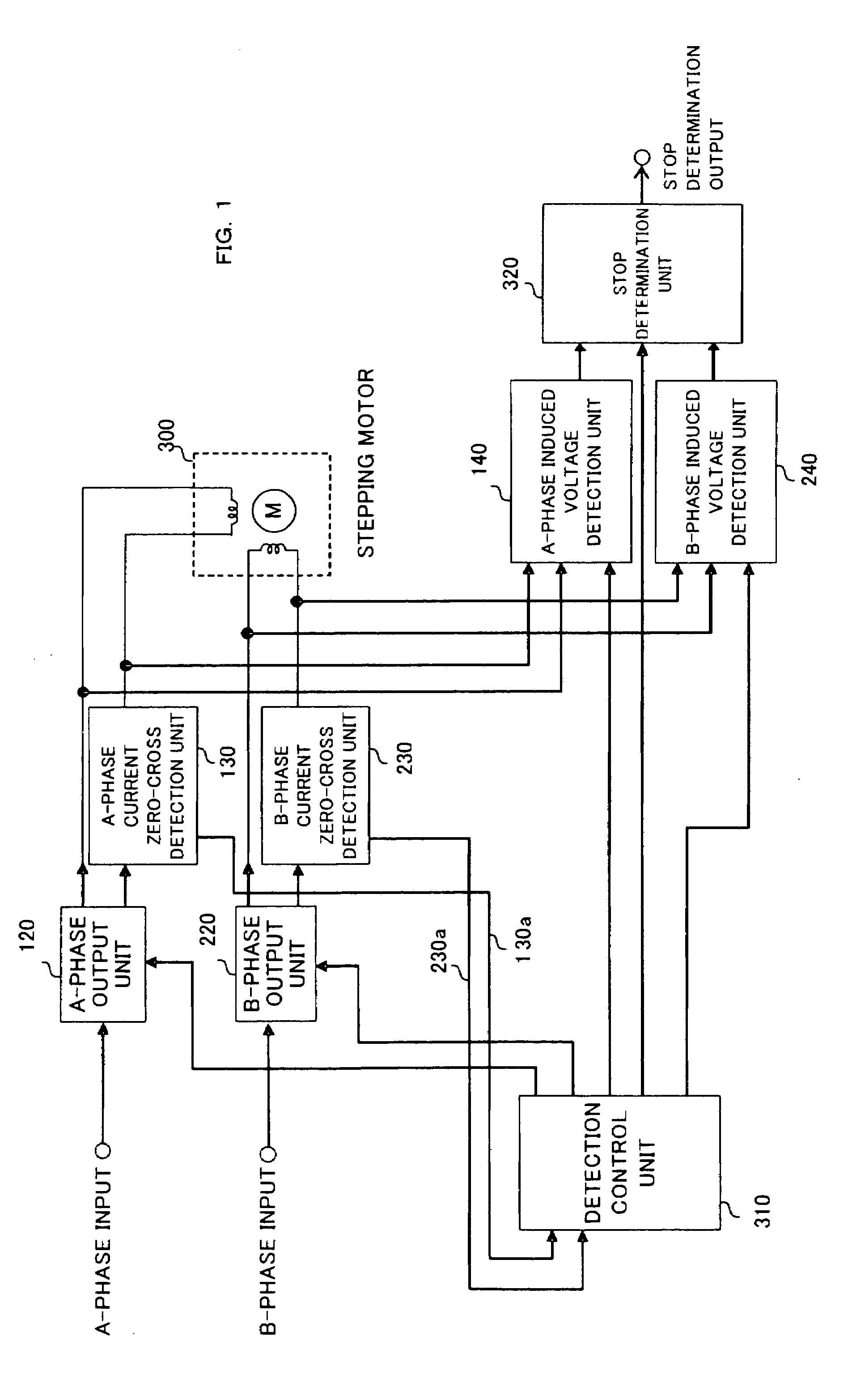
[0023]FIG. 1 is an explanatory drawing showing the present invention. In FIG. 1, reference numeral 300 denotes a two-phase bipolar stepping motor. An A-phase input signal and a B-phase input signal are fed with an analog signal having one of a sinusoidal wave and a triangular wave with a phase shift of 90° and digital information. In an A-phase output unit (120) and a B-phase output unit (220), the power transistors of one of the output units are driven so as to output a voltage or current obtained by multiplying the values of the A-phase input signal and the B-phase input signal by an optionally set gain.

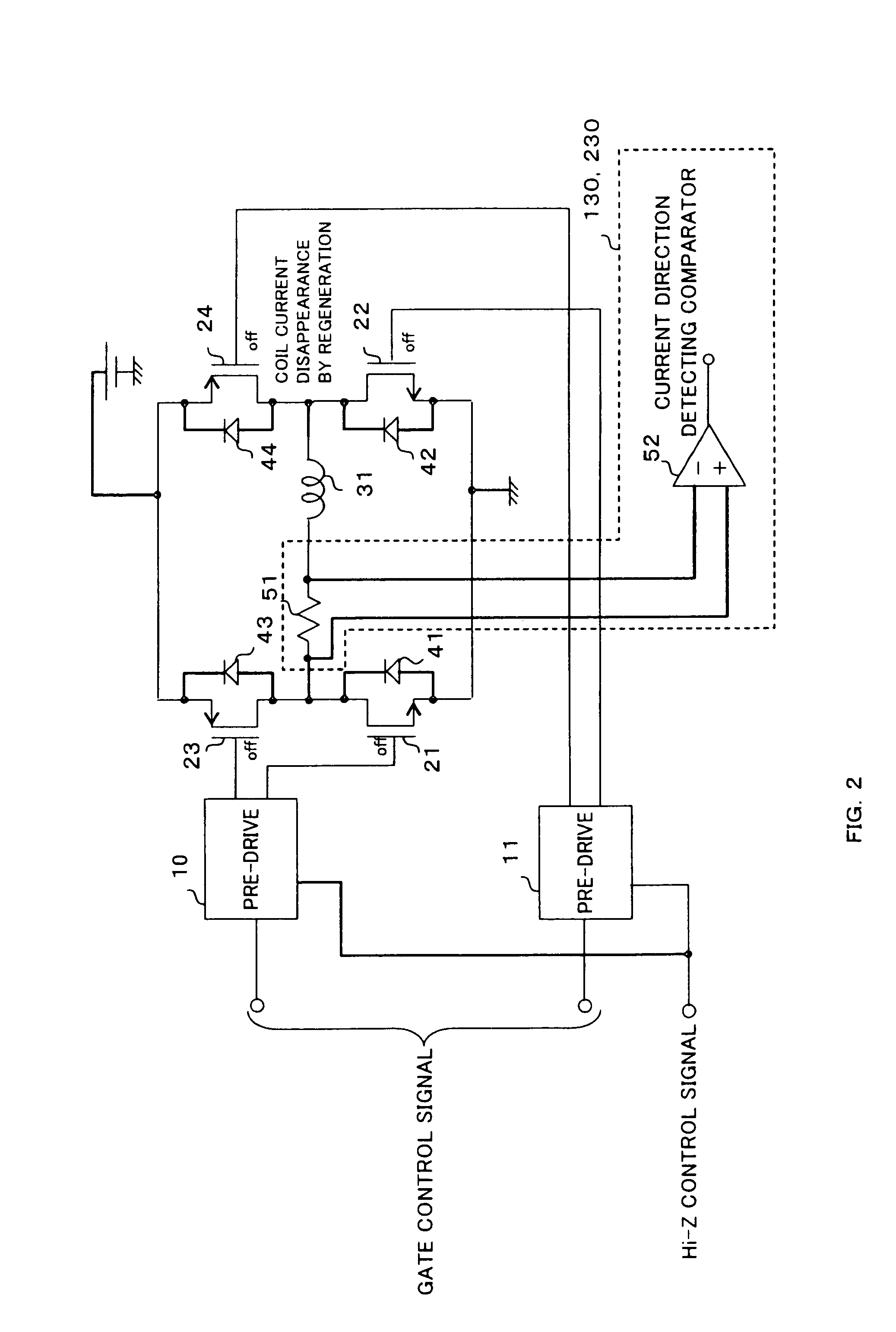
[0024]FIG. 2 shows an example of the configuration of the driven power transistor. FIG. 2 shows an H-bridge configuration for PWM driving. Diodes (41, 42, 43, 44) for regeneration are provided on a power supply and the ground from an output terminal connected to a motor coil (31). Power transistors (21, 22, 23, 24) are driven through pre-drives (10, 11). The power transistors have ...

second embodiment

[0030]FIG. 4 is an explanatory drawing showing the present invention. An A-phase current zero-cross detection unit (131) and a B-phase current zero-cross detection unit (231) which detect a current zero cross according to a clipped voltage during regeneration are connected to one output of an A-phase motor coil and one output of a B-phase motor coil, respectively. The A-phase current zero-cross detection unit (131) and the B-phase current zero-cross detection unit (231) output detection results of zero cross to a detection control unit (310). The detection control unit performs, as in the embodiment of FIG. 1, a sequence for detecting an induced voltage. FIG. 5 is an explanatory drawing of the A-phase current zero-cross detection unit (131) and the B-phase current zero-cross detection unit (231). When PWM driving of both chopping method is performed in an H-bridge circuit shown in FIG. 5, outputs Va and Vb connected to both ends of a coil (31) alternately repeat L output and H outpu...

third embodiment

[0031]FIG. 7 is an explanatory drawing showing the present invention. As in the embodiment of FIG. 1, reference numeral 300 denotes a two-phase bipolar stepping motor. To an A-phase input signal and a B-phase input signal, an analog signal having one of a sinusoidal wave and a triangular wave with a phase shift of 90° and digital information are inputted. An A-phase output unit (120) and a B-phase output unit (220) drive power transistors so as to output a current obtained by multiplying the values of the A-phase input signal and the B-phase input signal by a optionally set gain.

[0032]FIG. 8 shows, according to the third embodiment of the present invention, an input signal of each phase, an input threshold value of each phase, the output signal of the comparator of each phase, a voltage difference between coil terminals, a load current, an induced voltage, the rotation speed of a rotor, and the logic of stop determination output. The A-phase input signal and an A-phase input thresho...


PUM


Abstract

In a drive of a stepping motor, an electromotive force is generated on the coil of a motor with a sinusoidal wave having the same period as an energization period by smoothly rotating a rotor with microstep driving, and an induced power is stably detected by detecting the electromotive force at the zero cross of driving current. The detection around the current zero cross makes it possible to shorten a detection section, form a driving waveform with few distortions, and perform driving with a driving waveform as in an ordinary micro step. Thus a circuit is provided which is aimed at reducing noise, vibrations, and loss of synchronization, and increasing current consumption efficiency in the determination of stop.

Description

FIELD OF THE INVENTION[0001]The present invention relates to a stepping motor driver, and particularly relates to a stepping motor driver which determines whether an optical pickup is stopped or not in an optical disk device.BACKGROUND OF THE INVENTION[0002]Conventionally, before reading or writing data in an optical disk device, it is necessary to read disk information on the innermost end of a disk after power is turned on. However, an optical pickup is not always placed on a predetermined point because of disturbance. Thus the optical pickup is moved to one of the outermost end and the innermost end of the disk to adjust the offset of the position of the optical pickup, and then a reading sequence is started. In this movement to one of the outermost end and the innermost end, an optical sensor and a contact switch have been used to detect arrival at a destination. However, these components are more expensive than motor driver ICs. In order to reduce the cost of the overall optica...

Claims


Application Information

Patent Timeline
Patent Type & Authority Patents(United States)
IPC IPC(8): H02P8/12H02P8/00H02P8/22H02P8/38
CPCH02P8/22H02P8/34Y02P80/10
Inventor ARISAWA, DAIJIRO
Owner PANASONIC CORP
Why Eureka
Try Eureka