Automotive fuel system leak testing

a technology for fuel systems and leak detection, applied in the direction of combustion air/fuel air treatment, electric control, instruments, etc., can solve the problems of increasing increasing the cost of additional hardware and software, and increasing the cost of gas mileage. , to achieve the effect of reducing the amount of new hardware and/or software used for leak detection, reducing material and installation costs, and reducing the amount of hardware for leak detection

Active Publication Date: 2011-12-13
FORD GLOBAL TECH LLC
View PDF21 Cites 48 Cited by
  • Summary
  • Abstract
  • Description
  • Claims
  • Application Information

AI Technical Summary

Benefits of technology

[0005]In one example approach, an external vacuum pump may be used to create a vacuum to perform a leak test in a hybrid vehicle system. However, the inventors herein have recognized that such an approach may increase material and installation costs associated with the installation of such an external vacuum pump and associated hardware and software.
[0009]In this way, the amount of new hardware and / or software used for leak testing may be reduced, resulting in lower material and installation costs, since the fuel pump can be used for engine-off leak detection, as well as engine running fuel supply to the combustion chambers of the engine. Thus, the same pump may be used for leak testing and for supplying fuel to the engine, resulting in a reduced amount of hardware for leak detection. Additionally, vehicle gas mileage may be increased since, in this approach, leak testing may be performed without using the engine. Further, accuracy of a leak test may be increased since such an approach does not depend on pressure and temperature correlations, for example. Further still, shorter test times may be employed in this approach which may result in a greater amount of flexibility in deciding when a leak test may be implemented.

Problems solved by technology

However, the inventors herein have recognized that such an approach may increase material and installation costs associated with the installation of such an external vacuum pump and associated hardware and software.
However, the inventors herein have recognized that running the engine to perform leak tests when the engine is not used to propel the vehicle may result in a decrease in gas mileage since, in this example, fuel is consumed while performing the leak test.
However, the inventors herein have recognized a number of issues with such EONV approaches.
For example, additional hardware and software may increase costs, and long test times in may reduce the feasibility of carrying out a leak test.
Additionally, such EONV approaches may degrade during hot ambient temperature conditions.
Further, such EONV approaches may not be sufficiently accurate for leak testing, e.g., due to unreliable correlations between temperature and vacuum build (e.g., due to mass transfer between the liquid and vapor in a fuel tank).
Additionally, vehicle gas mileage may be increased since, in this approach, leak testing may be performed without using the engine.

Method used


Image

  • Automotive fuel system leak testing
  • Automotive fuel system leak testing
  • Automotive fuel system leak testing

Examples


Embodiment Construction

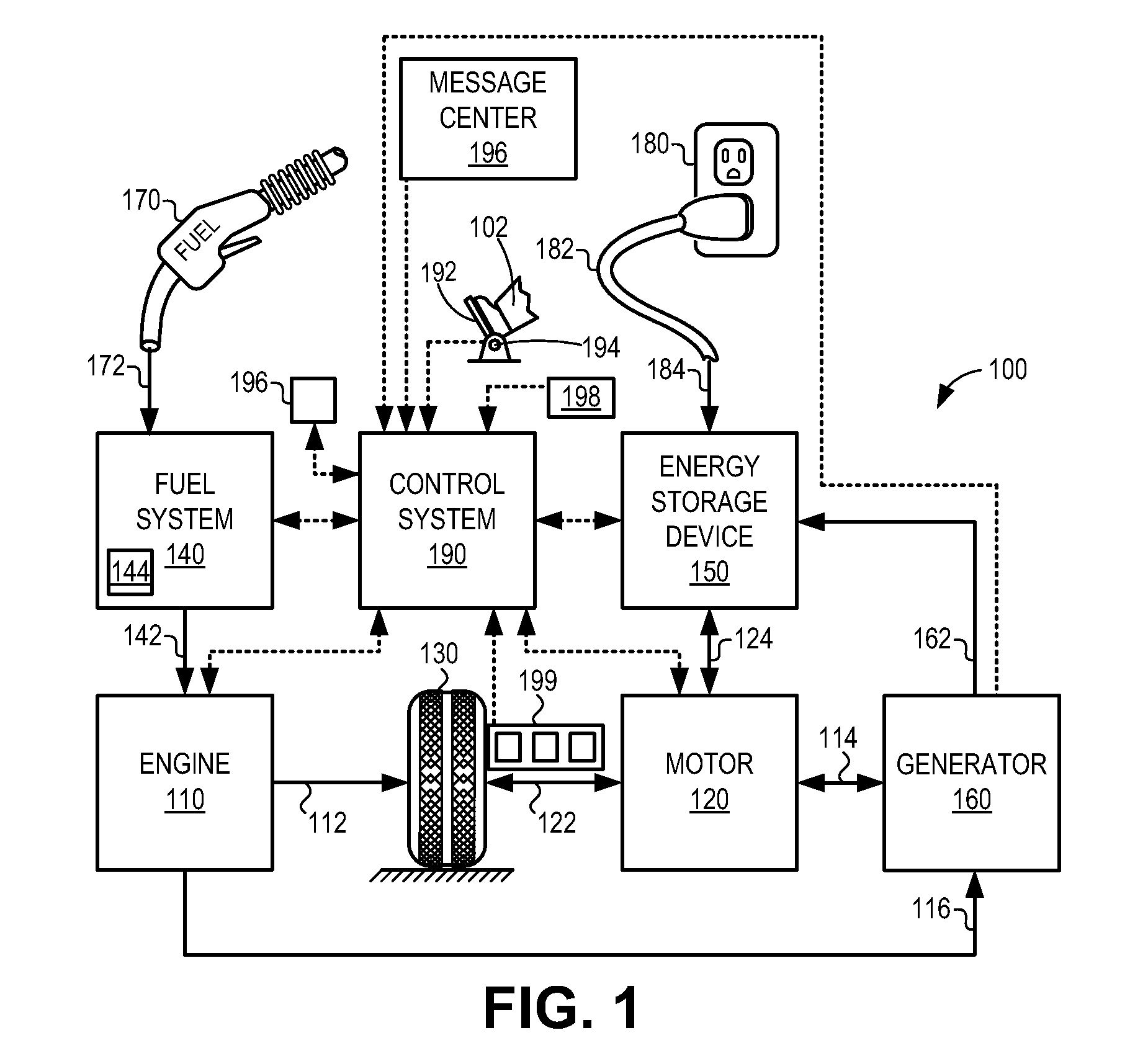
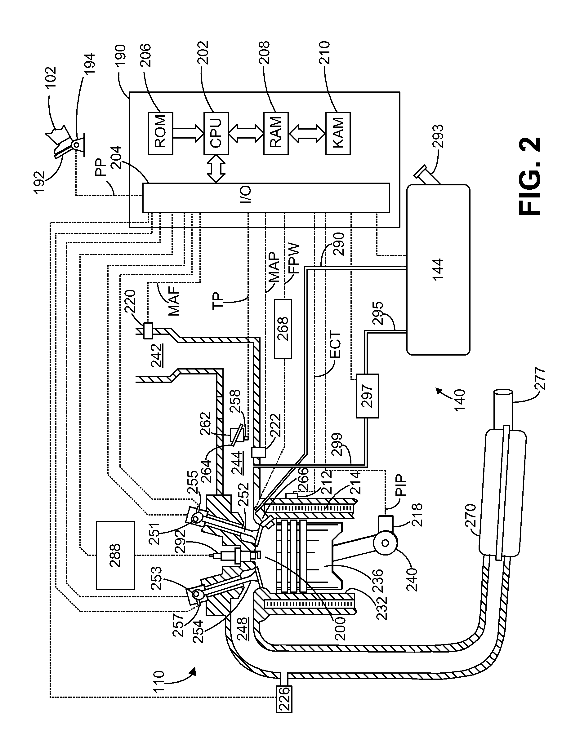
[0016]The following description relates to systems and methods for diagnosing fuel system leaks in hybrid vehicles, such as the example hybrid vehicle shown in FIG. 1. Such vehicles may include internal combustion engines fueled by a fuel system, such as shown in FIG. 2.

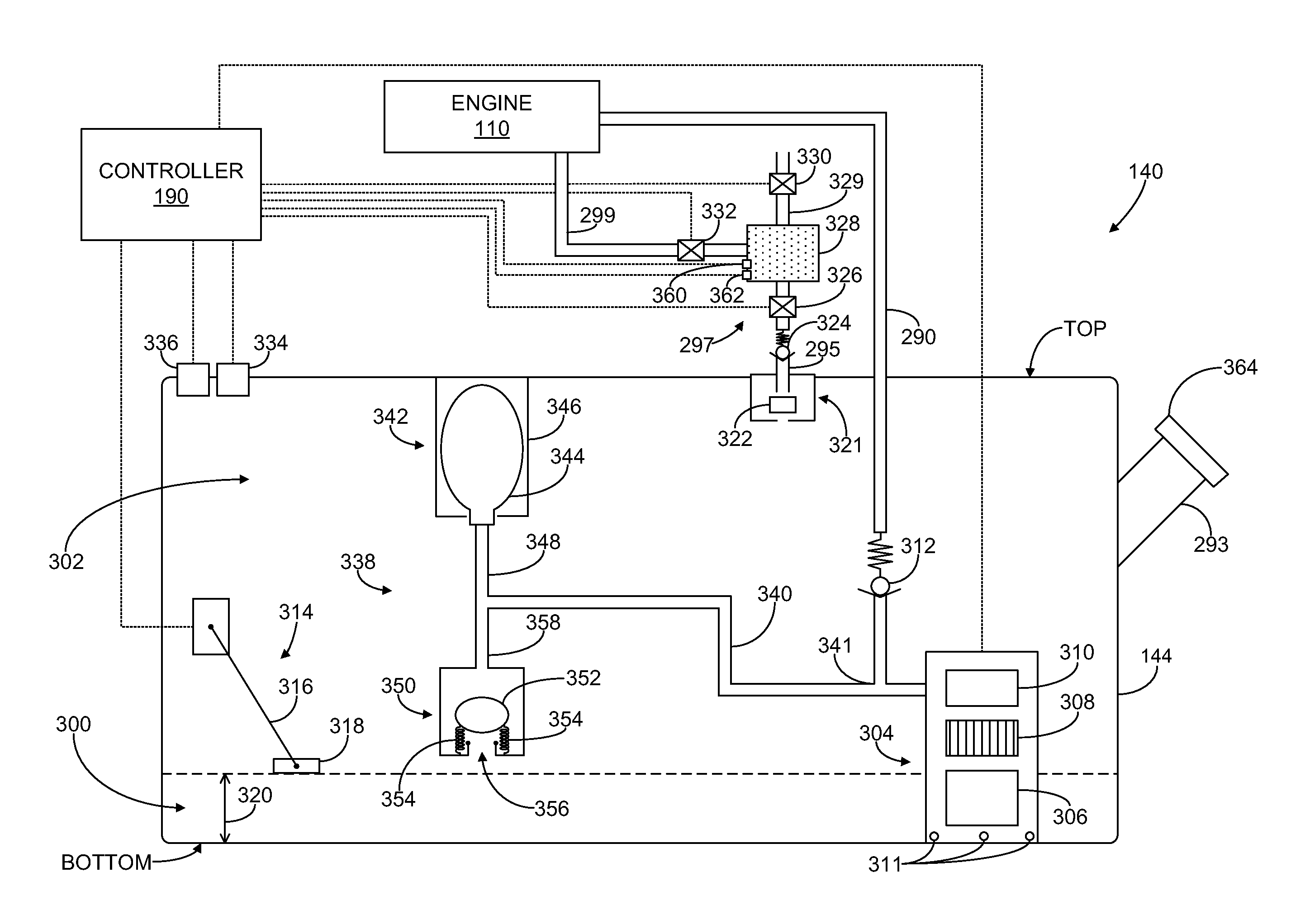
[0017]A leak detection system may be included within the fuel tank, such as shown in FIG. 3. Such a leak detection system may include a pressure accumulator which may be filled by a fuel pump in the fuel tank in order to create a vacuum in the fuel tank for diagnosing leaks. During certain conditions, the fuel pump may be used for leak testing whereas during other conditions, the same fuel pump may be used to deliver fuel to the engine. FIG. 4 shows an example method for diagnosing leaks in a fuel system including such a pressure accumulator. Leaks may be diagnosed in various components within a fuel system by monitoring pressure changes which occur during the leak testing. FIG. 5 shows example plots of such pressure...


PUM


Abstract

Systems and methods for performing leak testing on fuel system components in hybrid vehicles during engine-off operating conditions are disclosed. For example, a fuel tank may include a pressure accumulator which may be filled with fuel via a fuel pump in order to generate a vacuum which may be used to diagnose leaks in the fuel system.

Description

FIELD[0001]The present application relates to fuel system leak testing.BACKGROUND AND SUMMARY[0002]Fuel systems including fuel tanks may be used to store and provide fuel to engines. For example, a vehicle including an internal combustion engine may include a fuel tank that stores liquid fuels such as gasoline, diesel, methanol, ethanol, and / or other fuels.[0003]Liquid fuels in a fuel tank may evaporate into fuel vapors in the tank. As such, various fuel vapor management systems may be included in a fuel system. Such fuel systems may be substantially sealed from the atmosphere but may include components configured to vent the fuel system to the atmosphere during certain conditions. For example, a fuel system may include a vapor purge canister for filtering fuel vapors during venting.[0004]If there are leaks in the fuel system, e.g., if there are leaks in the fuel tank, canister or any other component of the vapor handling system, then fuel vapor may escape to the atmosphere contribu...

Claims


Application Information

Patent Timeline
Patent Type & Authority Patents(United States)
IPC IPC(8): F02M33/02G01M15/00
CPCF02M25/0818F02D41/042F02D41/3082
Inventor SIDDIQUI, SHAHID AHMED
Owner FORD GLOBAL TECH LLC
Why Eureka
Try Eureka