FMCW radar sensor

a radar sensor and sensor technology, applied in the field of fmcw radar sensors, can solve the problems of affecting the angular resolution capacity of the known radar sensor, the inability of the radar sensor to resolve the different azimuth angles of the two objects, and the inability to separate the spectrum in the spectrum, so as to improve the angular resolution capacity and minimize the phase jitter of the oscillator

Inactive Publication Date: 2011-12-13
ROBERT BOSCH GMBH
View PDF23 Cites 29 Cited by
  • Summary
  • Abstract
  • Description
  • Claims
  • Application Information

AI Technical Summary

Benefits of technology

[0016]In the near-field mode, on the other hand, the signals transmitted by the various antenna elements are decoupled from one another because of the frequency offset. This enables an additionally fanned out main lobe to be achieved, so that an enlarged location angle area comes about which also makes possible in the near field the location of objects having a greater lateral offset.
[0017]The switchover between the two modes may be managed very simply, in the radar sensor according to the present invention, by switching on and off the frequency offset. Thus, the sensor may be adapted in a simple manner to the respective application case, in optimal fashion. For instance, for trips involving greater speeds one may select the far-field mode, while at lower speeds, or in stop and go operation, switching is able to take place automatically to the near-field mode. Switching in rapid sequence between the two operating modes is also possible, so that the near field and the far field may be monitored almost simultaneously.
[0018]An additional advantage in the near-field mode is that, on the basis of the frequency offset, it is possible to distinguish, within the signal received from a single antenna element, between the portion of the signal that was transmitted by this antenna element itself and the portions of the signal transmitted by other antenna elements. Thus, for an individual radar object, for example, that is located in the overlapping region of two radar lobes, two peaks are now obtained in the spectrum of each of the two associated channels, one of which represents the direct echo, i.e., the signal that was transmitted by the respective antenna element and was also received by it again, while the other peak represents the so-called cross echo that was transmitted by the other antenna element. The frequency difference between these two peaks corresponds to the frequency offset between the transmitted signals. If, in the radar sensor according to the present invention, one evaluates the complex amplitudes only at the apex of each peak, for example, one consequently obtains altogether four complex amplitudes from the two antenna elements involved, in comparison with only two complex amplitudes in the case of the conventional sensor. A substantially higher number of measured values is thus available for determining the azimuth angle, which markedly improves the angular resolution capacity. In particular, even when evaluating the signals of only two radar lobes, it is now possible to resolve two angularly offset objects that have the same distance and the same relative speed. This measuring principle and evaluation principle as such is the subject matter of a parallel patent application filed by the Applicant and has as its title “Angle-Resolving Radar Sensor”.
[0019]The fact that the transmitting frequency is increased in at least one antenna element then yields the following additional advantage: As was explained above, the position of the signal generated by a radar object in the frequency spectrum is a function of the relative speed of the object and may thus, at certain relative speeds, also be shifted into the so-called DC range of the spectrum, i.e., into the frequency range surrounding the frequency zero, or even into the range of negative frequencies. It is not possible to detect or evaluate signal portions in the DC range using conventional FMCW radar sensors. In the complex intermediate frequency signal Z=|A|eift, positive and negative frequencies differ by the sign of frequency f. However, since in the conventional FMCW method, in the last analysis, only the absolute value of the real component of the intermediate frequency signal is evaluated, it is not possible to distinguish between positive and negative frequencies, so that the measuring result may be falsified if significant signal portions are in the negative spectral range. In the FMCW radar according to the present invention, at least in the near-field mode, the intermediate frequency signal for each channel is formed by mixing the signal received from the respective antenna element with a base signal, the frequency of which is at most equal to the smallest of the transmitting frequencies supplied to the different antenna elements. At least for one of the channels, the signal in the spectrum is therefore shifted by the frequency offset to positive frequencies so that the entire signal or at least a greater portion of it now lies in the positive frequency range capable of evaluation.
[0022]In order to minimize the phase jitter of the oscillators, it is expedient to provide a phase regulation for each oscillator, for instance, with the aid of a PLL (phase locked loop). It is also expedient, for the minimization of the phase jitter, if the transmission signals generated by the various oscillators are derived from a common reference signal that is generated by a very low-noise reference oscillator, preferably in a DRO (dielectric resonance oscillator).
[0023]In the far-field mode, no evaluation of cross echoes is possible in the simplest specific embodiment. However, in one refinement it is possible to combine the two operating modes in a meaningful way, by adapted algorithms in the signal processing, so that the angular resolution capacity is improved even in the far-field mode. One may, for instance, think of combining the antenna elements to form groups, and to supply the elements of each group with phase-offset transmission signals, even in the far-field mode. The switchover device then has the effect that the antenna elements from different groups corresponding to one another are supplied in the far-field mode with identical frequencies, and by contrast, in the near-field mode, also with frequencies that are offset to one another.

Problems solved by technology

Alternatively, however, the antenna elements may be so-called phased arrays made up of multiple sub-elements, which are supplied with transmission signals having such a phase relationship that the desired directional characteristic results by interference.
Now, if, for example, two objects which differ in their azimuth angle, but have the same distance and the same relative speed, then their signals can no longer be separated in the spectrum so that the radar sensor is unable to resolve the different azimuth angles of the two objects.
Another effect that impairs the angular resolution capacity of the known radar sensor results from the fact that the individual antenna elements do not generate sharply bundled beams, but rather relatively widely fanned radar lobes, due to diffraction and interference effects.
The FMCW radar sensor described above is generally not sufficient for this purpose, because in the near field the radar lobes are not yet fanned sufficiently widely, so that objects that are offset laterally are not able to be located.
Up to now, it has therefore been necessary to provide additional sensoric components for the near-field, to supplement the FMCW radar sensor, or to switch over between strongly and weakly bundling antennas or activation patterns for the phased arrays, which requires a relative complex design.
It is not possible to detect or evaluate signal portions in the DC range using conventional FMCW radar sensors.
In the complex intermediate frequency signal Z=|A|eift, positive and negative frequencies differ by the sign of frequency f. However, since in the conventional FMCW method, in the last analysis, only the absolute value of the real component of the intermediate frequency signal is evaluated, it is not possible to distinguish between positive and negative frequencies, so that the measuring result may be falsified if significant signal portions are in the negative spectral range.

Method used


Image

  • FMCW radar sensor
  • FMCW radar sensor
  • FMCW radar sensor

Examples


Embodiment Construction

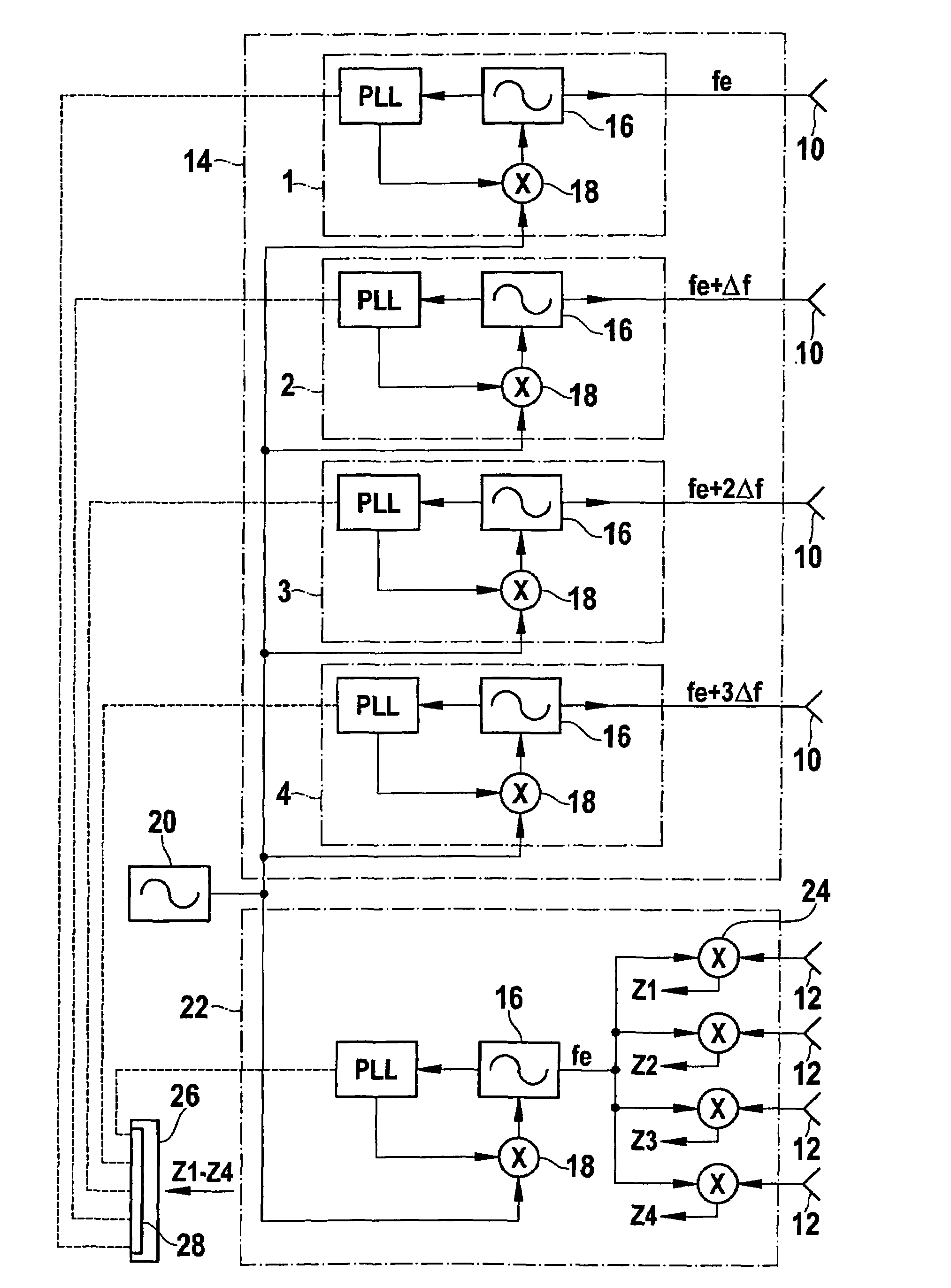
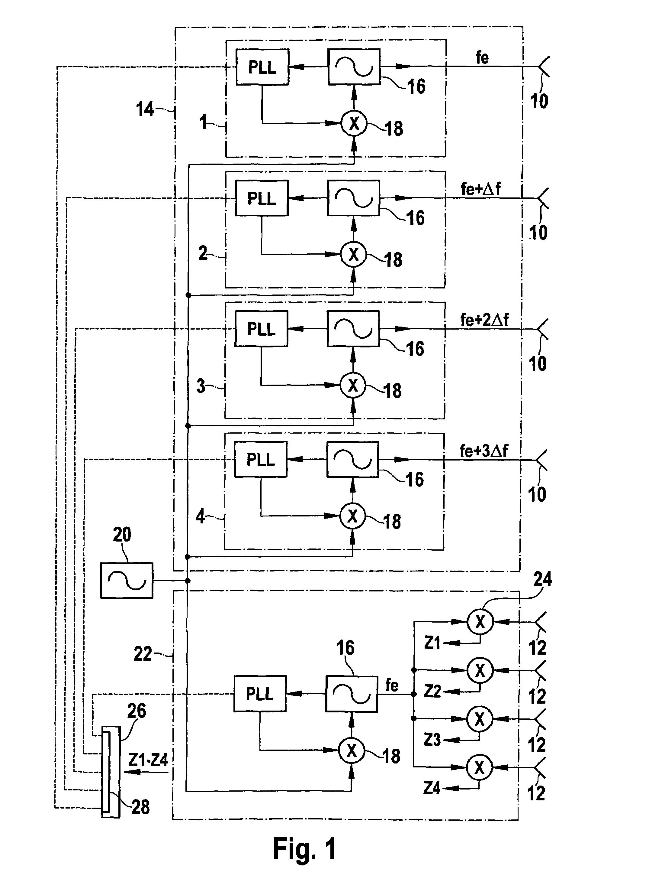
[0035]The FMCW radar sensor shown in FIG. 1 has four antenna elements 10 for transmitting the radar signals and four separate antenna elements 12 for receiving the signal reflected at the objects.

[0036]A supply circuit 14 is subdivided into four channels 1, 2, 3, 4, which are each assigned to one of antenna elements 10. Each channel includes a local oscillator 16 (VCO; voltage controlled oscillator) and a phase-coupling loop PLL (phase locked loop) for the phase regulation and phase stabilization of oscillator 16 via a mixer 18.

[0037]Mixers 18 of all four channels 1, 2, 3 and 4 receive a reference signal from a common reference oscillator 20, for instance, a DRO (dielectric resonance oscillator), which is distinguished by a very low phase jitter. The frequency of oscillators 16 is of the order of magnitude of 76 GHz, for example, while the frequency of reference oscillator 20 amounts to about a quarter of this. An intermediate frequency signal is supplied to each of mixers 18 by the...


PUM


Abstract

An FMCW radar sensor having a plurality of antenna elements and a supply circuit for supplying transmission signals having ramp-shaped modulated frequencies to the antenna elements, including a switchover device for switching over the supply circuit between a near-field mode, in which the transmission signals supplied to the individual antenna elements have a certain frequency offset, and a far-field mode, in which the frequencies of the transmission signals are identical.

Description

CROSS-REFERENCE TO RELATED APPLICATION[0001]This application was filed as International Patent Application No. PCT / EP2007 / 055718 on Jun. 11, 2007 and claims foreign priority benefits of German Patent Application No. 10 2006 032 539.7, filed Jul. 13, 2006.FIELD OF THE INVENTION[0002]The present invention relates to an FMCW radar sensor having a plurality of antenna elements and a supply circuit for supplying transmission signals having ramp-shaped modulated frequencies into the antenna elements.BACKGROUND INFORMATION[0003]Antenna elements may be individual antennas or patches, for example, which are offset with respect to the optical axis of a common radar lens. The directional characteristic of each antenna element, specifically the direction in the greatest radiation intensity or the greatest sensitivity, is then given by the offset of the respective element with respect to the optical axis. Alternatively, however, the antenna elements may be so-called phased arrays made up of mult...

Claims


Application Information

Patent Timeline
Patent Type & Authority Patents(United States)
IPC IPC(8): G01S13/08G01S13/93G01S13/931
CPCG01S13/345G01S13/931G01S2013/9325G01S2013/9321G01S2013/0245
Inventor WALTER, THOMASOLBRICH, HERBERTSTEINBUCH, DIRK
Owner ROBERT BOSCH GMBH
Why Eureka
Try Eureka