Apparatus for monitoring optical obstructions in an optical split network and method thereof

Inactive Publication Date: 2011-12-13
CHUNGHWA TELECOM CO LTD
View PDF2 Cites 19 Cited by
  • Summary
  • Abstract
  • Description
  • Claims
  • Application Information

AI Technical Summary

Benefits of technology

[0009]The objective of the present invention is to provide an apparatus and method of monitoring optical obstructions in an passive optical fiber network, cooperating to the deposition of the passive optical-fiber network service system in home. When the service system got a problem, the branch line may be monit

Problems solved by technology

As a result of the rapid growth of the global Internet, conventional networks cannot handle demands from high-speed data transformation applications due to the revolution in communication industry.
It is not easy to monitor optical fibers in a passive optical network according to an original design of branch line.
However, all divergent signals in a locus chart of the OTDR are overlapped and any one of the signals cannot thus be identified alone.
To solve such an identification problem, adding an additional active-identifying component is employed but the interaction between a communication network and a host computer in the central office is required, normally augmenting the complexity of the monitoring system; additional

Method used


Image

  • Apparatus for monitoring optical obstructions in an optical split network and method thereof
  • Apparatus for monitoring optical obstructions in an optical split network and method thereof
  • Apparatus for monitoring optical obstructions in an optical split network and method thereof

Examples


Embodiment Construction

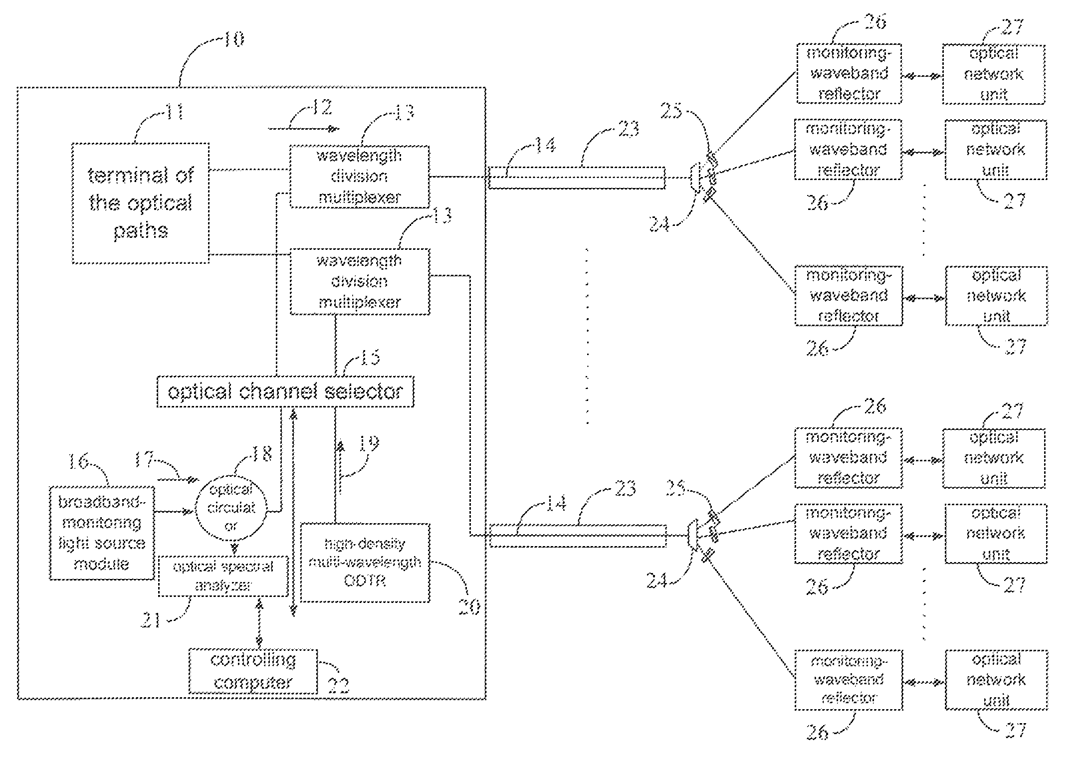
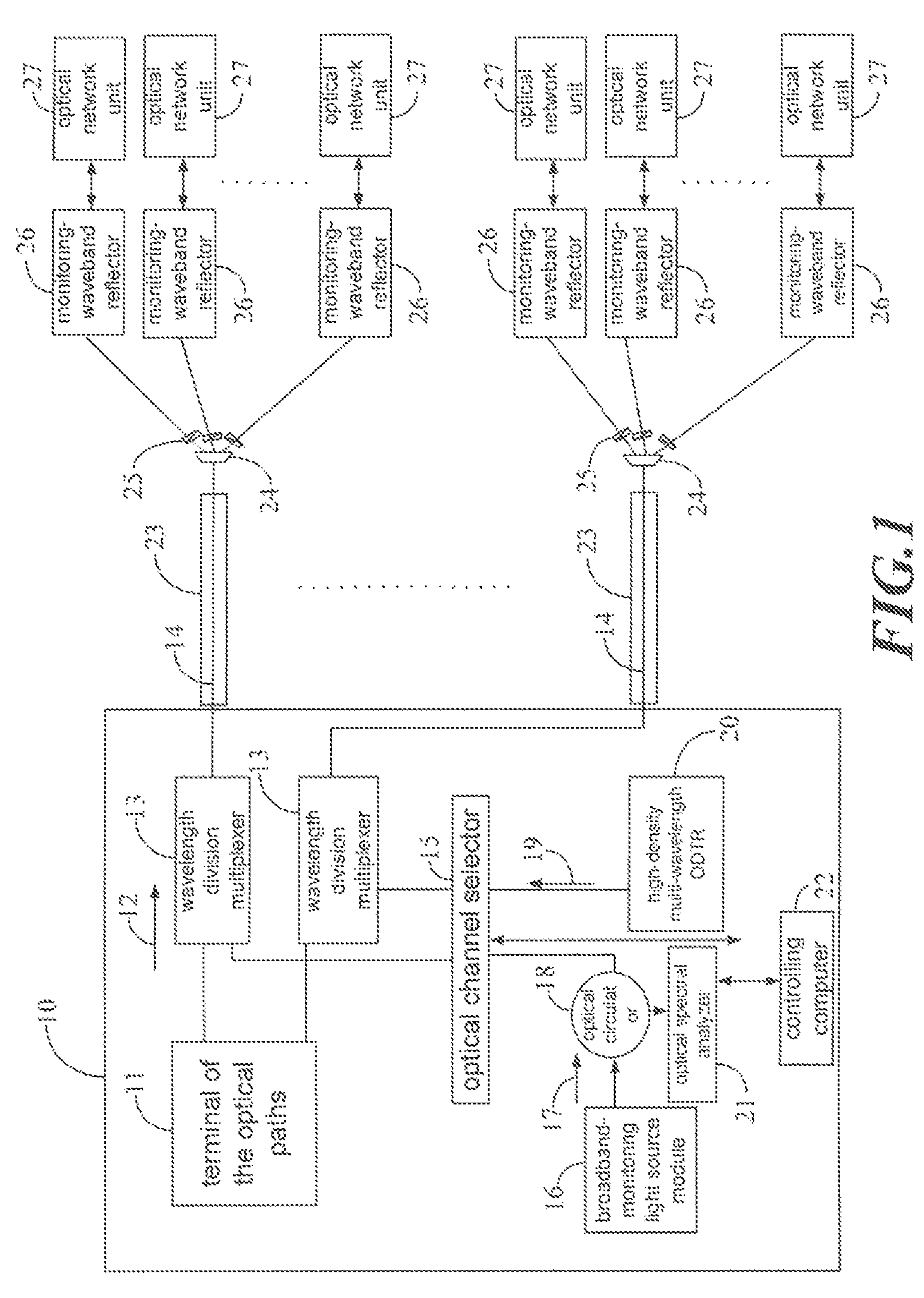
[0017]FIG. 1 shows a schematic diagram of the architecture of an apparatus and method of monitoring optical obstructions in an passive optical network of the present invention that comprises:

[0018]A broadband-monitoring light source module 16 for continuously transmitting a light source of the monitored waveband 17;

[0019]An optical circulator 18 for coupling with the light sent by the broadband-monitoring light source module 16, delivering the light into an optical network, and then receiving a monitoring light reflected back from the optical network and subsequently sending it into the optical spectrum analyzer 21;

[0020]An optical channel selector 15 for connecting to monitoring apparatuses and each optical fiber route;

[0021]A wavelength division multiplexer 24 for integrating the optical signals of the service waveband 12 and the monitored waveband 17 and delivering it into the optical fiber 14;

[0022]A specific wavelength optical filter 25 for filtering a specified monitored wavel...


PUM


Abstract

An apparatus and method for monitoring optical fiber obstructions in an optical split network is described. The monitoring apparatus comprises a broadband-monitoring light source module, an optical circulator, an optical spectral analyzer, a high-density multi-wavelength OTDR, a controlling computer, a wavelength division multiplexer, a specific wavelength optical filter, a monitoring-waveband reflector, and an optical channel selector. The monitoring apparatus utilizes the specific wavelength optical filter and the monitoring-waveband reflector to collectively construct an optical split network optical fiber obstruction monitoring apparatus for the passive optical network having multiple split routes by filtering, reflecting, and transmitting coming lights, so as to achieve the purposes of locating the obstructed split routes and obstruction locations at the same time.

Description

BACKGROUND OF THE INVENTION[0001]1. Field of the Invention[0002]The present invention relates to an apparatus and method for monitoring optical obstructions in a passive optical network; and, particularly, relates to an apparatus and method for monitoring optical fibers and measuring obstruction locations in a passive optical network by integrating optical filters having specific wavelength and monitoring a monitoring-waveband reflector to filter and reflect inputting lights, achieving the simplicity and high efficiency.[0003]2. Description of the Prior Art[0004]As a result of the rapid growth of the global Internet, conventional networks cannot handle demands from high-speed data transformation applications due to the revolution in communication industry. Technologies in the developed optoelectronics industry and various applications for different products have timely provided a best solution in response to a demand for large bandwidth in the rapid growth of the global Internet, hi...

Claims


Application Information

Patent Timeline
IPC IPC(8): G01N21/88
CPCG01M11/3136
Inventor WANG, CHIH-YIHLIAW, TAY-JANGWANG, SHENG-WEITSAI, FWU-YUANWU, CHIA-HSIEN
Owner CHUNGHWA TELECOM CO LTD
Why Eureka
Try Eureka