Spatial light modulator with structured mirror surfaces

a mirror surface and spatial light technology, applied in the field of micromechanical reflecting slms, can solve the problems of incoherence, light is typically not coherent, and the operation speed is more limited by the data loading speed, and achieve the effects of improving slms, high precision, and simple system architectur

Active Publication Date: 2011-12-13
MICRONIC LASER SYST AB
View PDF69 Cites 6 Cited by
  • Summary
  • Abstract
  • Description
  • Claims
  • Application Information

AI Technical Summary

Problems solved by technology

They can be built in large arrays of many million mirrors and the operating speed is more limited by the data loading speed than the operation of the mirrors themselves, since each mirror may operate in the hundreds of kilohertz or even megahertz range.
When TI's DMDs are used, the light is typically not coherent between mirrors; in piston-type SLMs it must be coherent; and in Silicon Light Machines' devices it may or may not be coherent between pixels depending on the device and the system design.
Some applications are best served by a SLM with a coherent illumination source and, therefore, are not well served by the DMD.
However, the applications overlap.
Moreover, in some applications neither type is perfect, since what is needed is really a fully complex device which can modulate both magnitudes and phases.

Method used


Image

  • Spatial light modulator with structured mirror surfaces
  • Spatial light modulator with structured mirror surfaces
  • Spatial light modulator with structured mirror surfaces

Examples


Embodiment Construction

[0051]The following detailed description is made with reference to the figures. Preferred embodiments are described to illustrate the present invention, not to limit its scope, which is defined by the claims. Those of ordinary skill in the art will recognize a variety of equivalent variations on the description that follows.

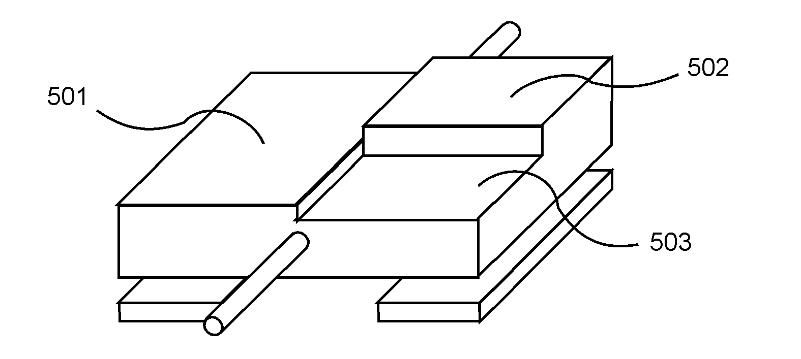
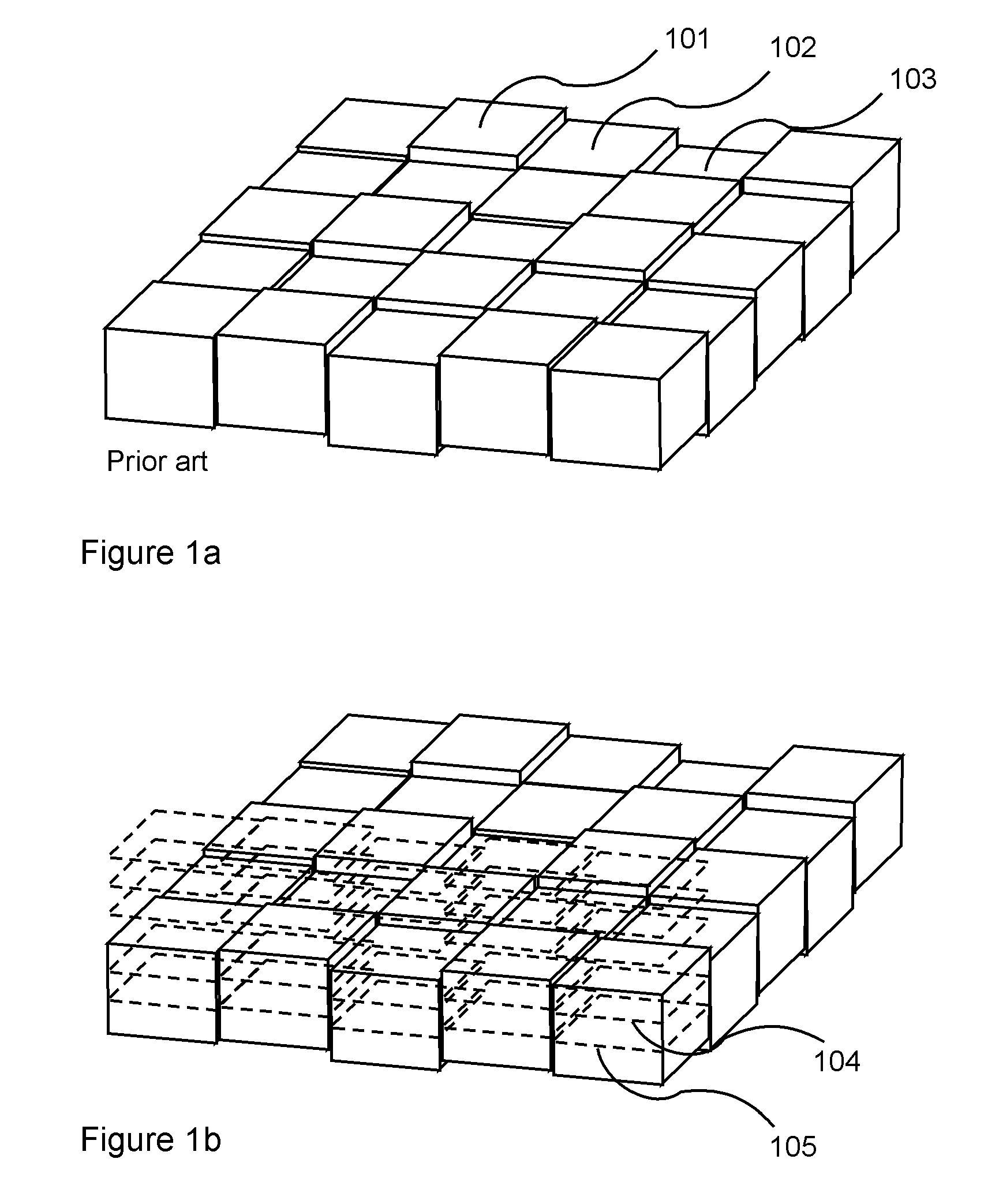
[0052]FIG. 1 shows a spatial light modulator in prior art. It has an array of pixels, which can be one or two dimensional, dense or interspersed with passive areas. Each pixel, which may be a mirror, may move up or down so that a light field which impinges from the top, is reflected with a different phase depending on the height of the mirror or pixel. Mirror arrays as the one in FIG. 1a are used for wavefront correction, signal processing, beam steering, and for lithography as discussed above. The height of each pixel is calculated beforehand and the height information, e.g., in the form of a voltage, is fed to the actuators moving the mirrors up and down creati...


PUM


Abstract

The invention relates to methods to improve SLMs, in particular to reflecting micromechanical SLMs, for applications with simple system architecture, high precision, high power handling capability, high throughput, and / or high optical processing capability. Applications include optical data processing, image projection, lithography, image enhancement, holography, optical metrology, coherence and wavefront control, and adaptive optics. A particular aspect of the invention is the achromatization of diffractive SLMs so they can be used with multiple wavelengths sequentially, simultaneously or as a result of spectral broadening in very short pulses.

Description

RELATED APPLICATION[0001]This application claims the benefit U.S. Provisional Patent Application No. 61 / 047,715 Apr. 24, 2008. The related application is incorporated by reference.BACKGROUND OF THE INVENTION[0002]SLMs can be transmissive or reflective, based on micromechanical shutters or mirrors, or on reflecting liquid crystals or other electro-optical cells. Much of this invention relates to micromechanical reflecting SLMs, i.e. micromirror arrays. Reflecting micromechanical SLMs have the advantage that they can be inexpensive and stable, and can have high power handling capability and a very high data rate. They can be built in large arrays of many million mirrors and the operating speed is more limited by the data loading speed than the operation of the mirrors themselves, since each mirror may operate in the hundreds of kilohertz or even megahertz range. Were it not for the bottleneck of bringing the data on to the chip a micromirror array could easily operate at 1012 pixel op...

Claims


Application Information

Patent Timeline
Patent Type & Authority Patents(United States)
IPC IPC(8): G02B26/00G03B27/42
CPCG02B5/1809G02B26/06G02B26/0841G03F7/70291G02B5/1861G02B26/0808
Inventor SANDSTROM, TORBJORN
Owner MICRONIC LASER SYST AB
Why Eureka
Try Eureka