B1 mapping in MRI system using k-space spatial frequency domain filtering

a spatial frequency domain and mapping technology, applied in the field of generating multidimensional maps of the spatial distribution of radio frequency magnetic fields, can solve the problems of introducing unwanted effects of rf fields, inability to achieve absolutely uniform homogeneity, and inability to achieve absolute linear gradients, etc., to achieve a higher resolution b1 map

a spatial frequency domain and mapping technology, applied in the field of generating multidimensional maps of the spatial distribution of radio frequency magnetic fields, can solve the problems of introducing unwanted effects of rf fields, inability to achieve absolutely uniform homogeneity, and inability to achieve absolute linear gradients, etc., to achieve a higher resolution b1 map

US8077955B2Active Publication Date: 2011-12-13TOSHIBA MEDICAL SYST CORP

Image

  • B1 mapping in MRI system using k-space spatial frequency domain filtering
  • B1 mapping in MRI system using k-space spatial frequency domain filtering
  • B1 mapping in MRI system using k-space spatial frequency domain filtering

Examples


Embodiment Construction

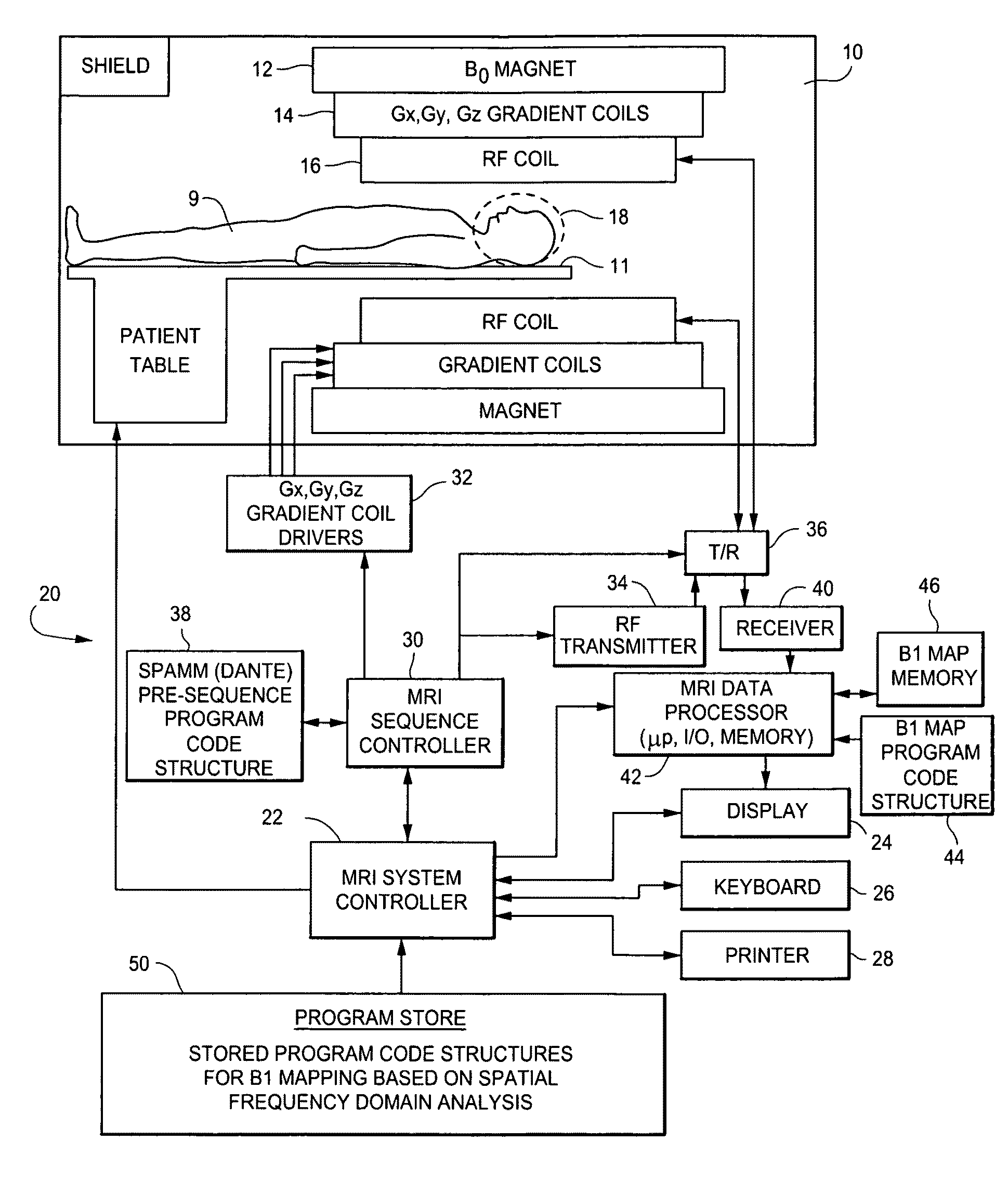
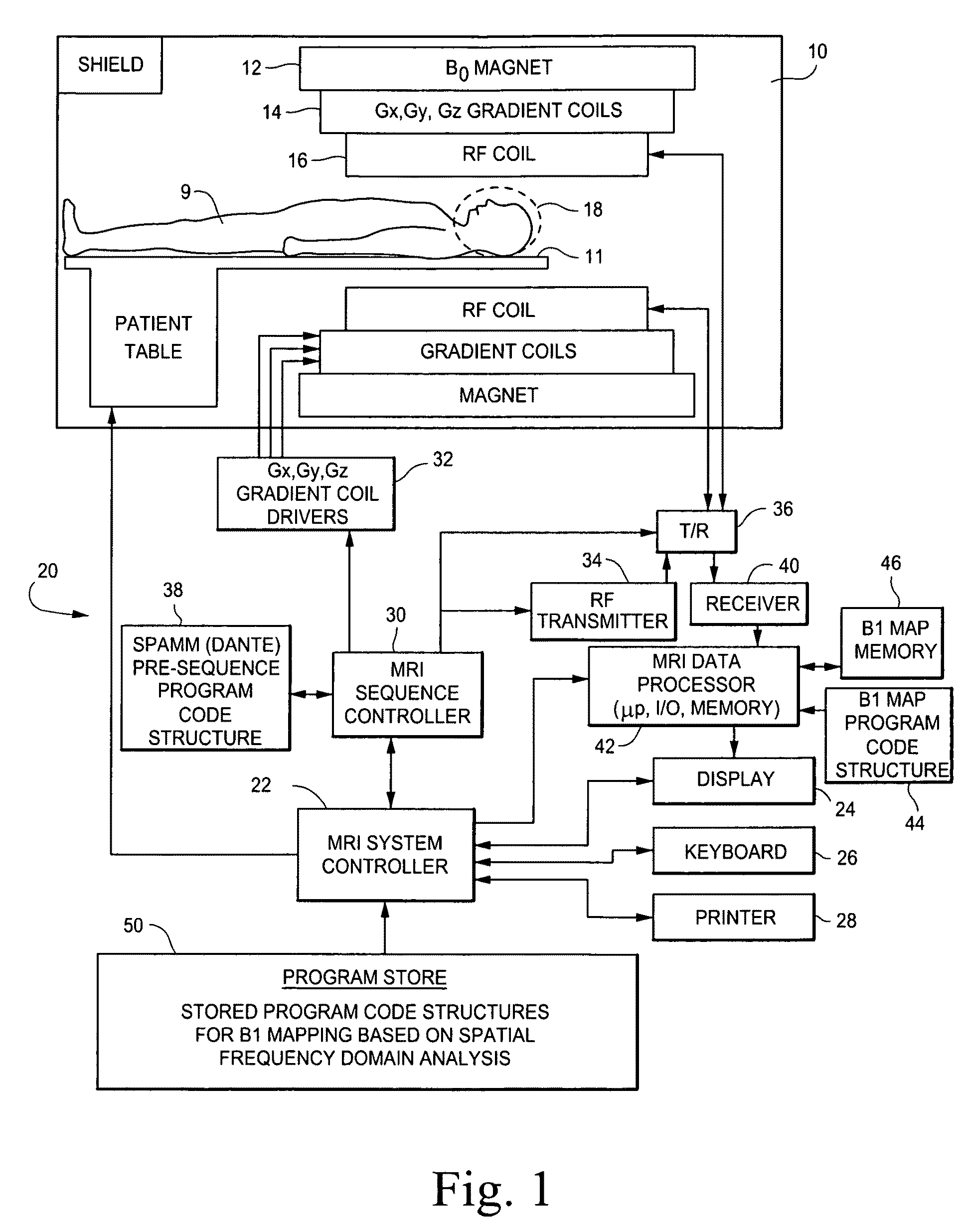
[0106]The MRI system shown in FIG. 1 includes a gantry 10 (shown in schematic cross-section) and various related system components 20 interfaced therewith. At least the gantry 10 is typically located in a shielded room. One MRI system geometry depicted in FIG. 1 includes a substantially coaxial cylindrical arrangement of the static field B0 magnet 12, a Gx, Gy and Gz gradient coil set 14 and an RF coil assembly 16. Along the horizontal axis of this cylindrical array of elements is an imaging volume 18 shown as substantially encompassing the head of a patient 9 supported by a patient table 11.

[0107]An MRI system controller 22 has input / output ports connected to display 24, keyboard 26 and printer 28. As will be appreciated, the display 24 may be of the touch-screen variety so that it provides control inputs as well.

[0108]The MRI system controller 22 interfaces with MRI sequence controller 30 which, in turn, controls the Gx, Gy and Gz gradient coil drivers 32, as well as the RF transm...


PUM


Abstract

Frequency filtering of spatially modulated or “tagged” MRI data in the spatial frequency k-space domain with subsequent 2DFT to the spatial domain and pixel-by-pixel arithmetic calculations provide robust ratio values that can be subjected to inverse trigonometric functions to derive B1 maps for an MRI system.

Description

BACKGROUND[0001]1. Technical Field[0002]This application describes methods and apparatus for generating multi-dimensional maps of the spatial distribution of radio frequency (RF) magnetic fields (typically labeled as the “B1” field) in MRI (magnetic resonance imaging) systems.[0003]2. Related Art[0004]Magnetic resonance imaging (MRI) systems are by now well known and many different types of commercially available MRI systems are regularly employed for medical research and / or diagnostic purposes. Although there are many variations in detailed image acquisition processes and / or MRI system geometries, they all share some basic fundamental principles.[0005]For example, MRI systems all utilize the principle of nuclear magnetic resonance (NMR) wherein nuclei having a net magnetic moment (e.g., nuclei having an odd number of protons such as the hydrogen nucleus) are immersed in a static background magnetic field B0. Ideally, this background static magnetic field is homogeneous throughout a...

Claims


Application Information

Patent Timeline
13 Dec 2011
Publication
US8077955B2
IPC
G06K9/00; G01R33/54
CPC
G01R33/246; G06T11/003; G01R33/56333; G01R33/443
Inventors
DANNELS, WAYNE R.; WHEATON, ANDREW J.