Optical cable module and apparatus using the same

a technology of optical cable module and optical waveguide, which is applied in the direction of optical waveguide light guide, bundled fibre light guide, instrument, etc., can solve the problems of large loss difference due to the change in optical waveguide, change in optical path conversion loss, spot-size mismatching loss,

Inactive Publication Date: 2011-12-13
ORMON CORP
View PDF31 Cites 4 Cited by
  • Summary
  • Abstract
  • Description
  • Claims
  • Application Information

AI Technical Summary

Benefits of technology

[0014]In this manner, while the angle distribution of signal light is changed on the light-releasing side of the optical waveguide, the rate of the signal light to be taken out by the optical path conversion mirror is changed. That is, in the case of the optical path conversion mirror formed by diagonally cutting off the end portion of the optical waveguide, with respect to light rays that are made incident on the cut-off end face with an angle smaller than the critical angle, those light rays that are allowed to transmit the optical path conversion mirror are generated. Here, upon having a change in the angle distribution of the signal light on the light-releasing side, the distribution of incident angle of light onto the optical path conversion mirror is of course changed, resulting in a change in the rate of the signal light to be transmitted through the optical path conversion mirror. More specifically, as the angle distribution of the signal light expands, the rate of the signal light to be transmitted through the optical path conversion mirror increases. That is, the optical path conversion loss in the optical path conversion mirror increases.
[0018]The present invention has been devised in view of the above-mentioned problems, and its objective is to achieve an optical cable module that can suppress variations in light quantity of signal light caused by a shape change in an optical waveguide.
[0022]In contrast, in accordance with the above-mentioned structure, the center of the light-receiving element is placed with a gap from a first position (light axis reflection position) at which light transmitted through the center of the cross section of the light axis of the core is reflected by the optical path conversion mirror to reach the light-receiving face. With this arrangement, in the light-receiving element, the area where signal light is cut off by the optical path conversion mirror is made as small as possible so as not to be included therein, and both of the light-receiving profile without a bending in the optical waveguide and the light-receiving profile with a bending in the optical waveguide can be received without causing a spot size mismatching loss.

Problems solved by technology

Moreover, these changes in the light wave conditions cause a change in the optical path conversion loss and a change in the spot-size mismatching loss.
That is, in the conventional optical waveguide, a problem arises in which a large loss difference occurs due to the change in the optical waveguide.

Method used


Image

  • Optical cable module and apparatus using the same
  • Optical cable module and apparatus using the same
  • Optical cable module and apparatus using the same

Examples


embodiment 1

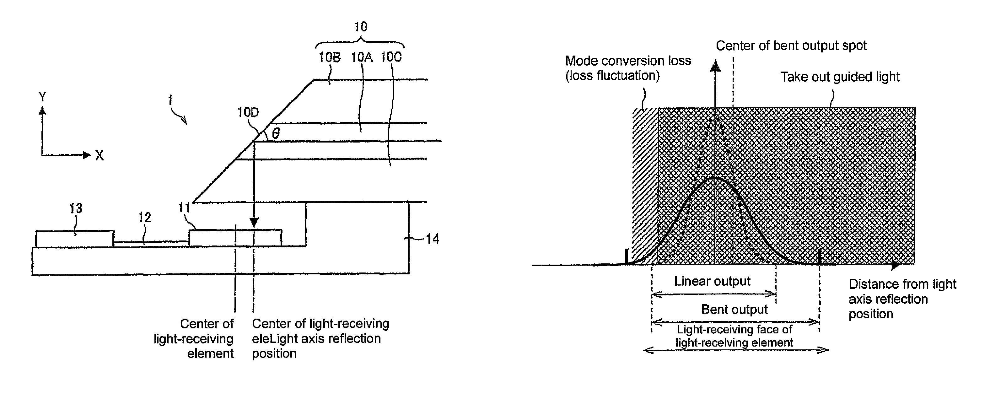
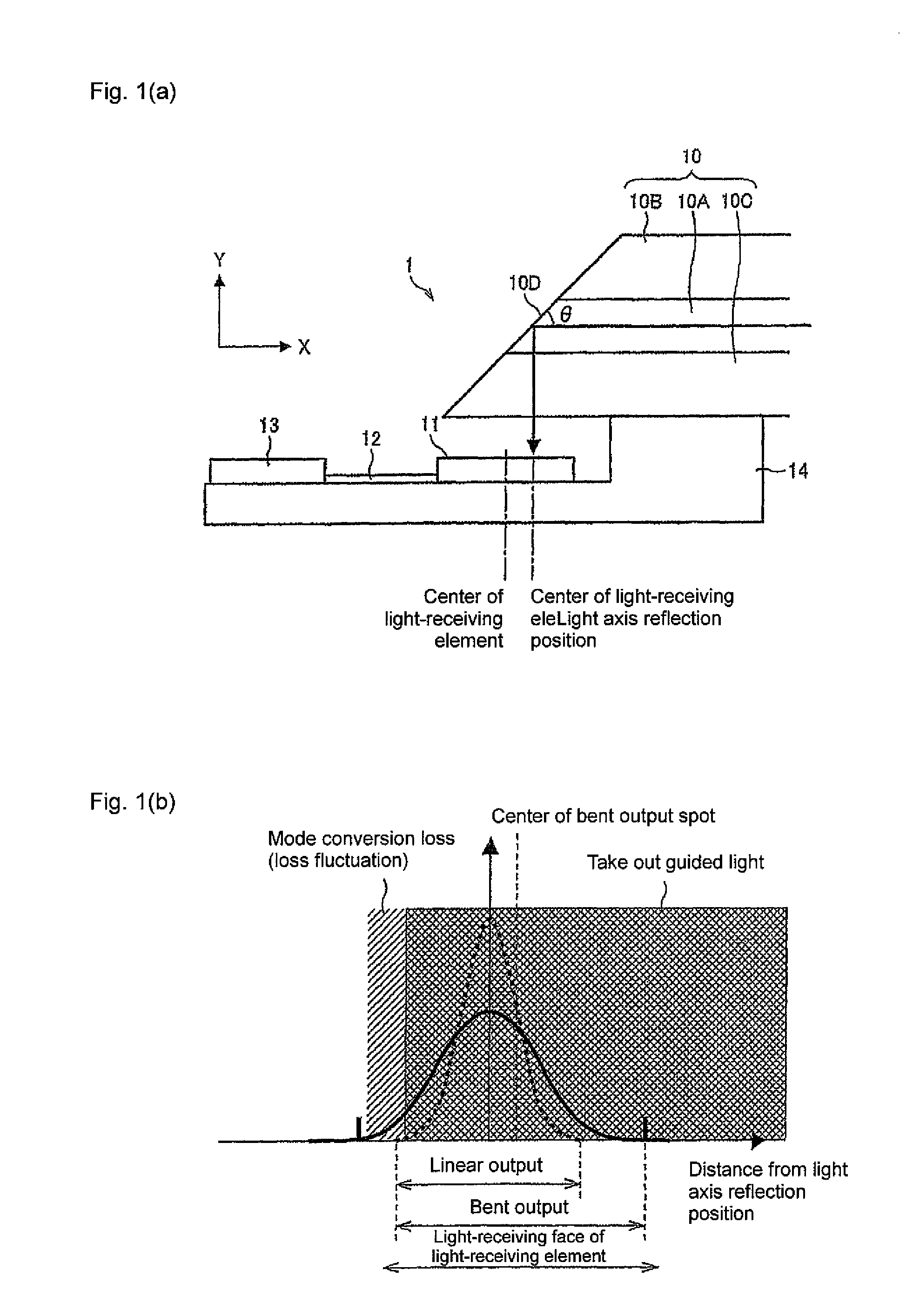
[0040]Referring to drawings, the following description will discuss one embodiment of the present invention. First, referring to FIGS. 1(a) and 1(b), one structural example of an optical cable module according to embodiment 1 will be described.

[0041]An optical cable module 1 shown in FIG. 1(a) is mainly configured by an optical waveguide 10, a light-receiving element 11 and a supporting substrate 14 on its end portion on the light-releasing side. The end portion of the optical waveguide 10 is secured onto the supporting substrate 14 by a bonding process or the like, and the end portion of the optical waveguide 10 and the light-receiving element 11 are secured in the relative positional relationship thereof. Moreover, the optical cable module 1 may be provided with an electric wire 12 and an electrical connection unit 13 so as to easily take out an electric signal outputted by the light-receiving element 11.

[0042]Here, the end portion of the optical cable module 1 on the reversed sid...

embodiment 2

[0060]Referring to Drawings, the following description will discuss another embodiment of the present invention. First, referring to FIGS. 5(a) and 5(b), one structural example of an optical cable module according to embodiment 2 will be described.

[0061]An optical cable module 3 shown in FIG. 5(a) is mainly configured by an optical waveguide 30, a light-receiving element 31 and a supporting substrate 34 on its end portion on the light-releasing side. The end portion of the optical waveguide 30 is secured onto the supporting substrate 34 by a bonding process or the like, and the end portion of the optical waveguide 30 and the light-receiving element 31 are secured in their relative positional relationship. Moreover, the optical cable module 3 may be provided with an electric wire 32 and an electrical connection unit 33 so as to easily take out an electric signal outputted by the light-receiving element 31.

[0062]Here, in the same manner as in the optical waveguide 30 of the optical ca...


PUM


Abstract

An optical cable module is mainly provided with: an optical waveguide (10), a light-receiving element (11) and a supporting substrate (14) at its end portion of the light releasing side. The end portion of the optical waveguide (10) is fixed in its relative positional relationship with the light-receiving element (11). The end face of the optical waveguide (10) is not made perpendicular to the light axis (X-axis), and is diagonally cut so as to form an optical path conversion mirror (10D). Assuming that a light ray (indicated by a solid line in the Figure) that passes through the center of the light-axis cross section of a core (10A), and is reflected by the optical path conversion mirror (10D), and then reaches a light-receiving face at a light axis reflection position, the center of the light-receiving element (11) is placed with a gap from the light axis reflection position, in the optical cable module (1).

Description

TECHNICAL FIELD[0001]The present invention relates to an optical cable module using an optical waveguide, and more particularly to an optical cable module using an optical waveguide having high flexibility.BACKGROUND ART[0002]In recent years, an optical communication network capable of executing data communication with a large capacity at high speeds has been expanded. It is expected that, from now on, this optical communication network will be installed not only among apparatuses, but also in apparatuses. Here, in order to achieve a printed circuit board by using optical wiring, an optical waveguide that can be formed into an array has been highly expected.[0003]The optical waveguide is formed by a core having a high refractive index and a clad having a low refractive index, which is formed in contact with the periphery of the core so that a light signal that is made incident on the core is transmitted, while being repeatedly total-reflected by the border between the core and the c...

Claims


Application Information

Patent Timeline
Patent Type & Authority Patents(United States)
IPC IPC(8): G02B6/26
CPCG02B6/262G02B6/4202G02B6/10G02B6/14G02B6/4214G02B6/43G02B6/122G02B6/42
Inventor HAMANA, KENTAROENAMI, AKIRAYASUDA, NARUHOSOKAWA, HAYAMI
Owner ORMON CORP
Why Eureka
Try Eureka