Frequency stability measuring apparatus

a technology of frequency stability and measuring apparatus, which is applied in the direction of measurement devices, oscillator generators, instruments, etc., can solve the problems of increasing measurement errors, long time before starting measurement, and inconvenient quadrature detection as a method for measuring all oscillators mass-produced, etc., to increase the slew rate of the signal input, increase the frequency resolution, and improve the effect of frequency stability

Inactive Publication Date: 2007-03-08
SEIKO EPSON CORP
View PDF3 Cites 13 Cited by
  • Summary
  • Abstract
  • Description
  • Claims
  • Application Information

AI Technical Summary

Benefits of technology

[0010] An advantage of the invention is to provide a frequency stability measuring apparatus in which a waveform-shaping circuit is inserted between a filter and a counter to increase the slew rate of a signal inputted to a counter and thus to increase a frequency resolution to enhance the stability of measurement.
[0011] According to one aspect of the invention, a frequency stability measuring apparatus for measuring a frequency fluctuation of a signal outputted from a given signal source includes: a reference signal output unit that outputs a reference frequency signal; a mixer that mixes a signal outputted from the signal source with the reference frequency signal outputted from the reference signal output unit and outputs a resultant signal; a filter that allows a low-frequency component of the signal outputted from the mixer to pass therethrough; a waveform-shaping circuit that shapes a waveform of a signal outputted from the filter; a counter that counts a number of pulses of a signal shaped by the waveform-shaping circuit; and a control unit that calculates average frequencies of the signal outputted from the filter within respective measurement periods of a predetermined length, and calculates and outputs a standard deviation of the average frequencies calculated.
[0012] A feature of this aspect of the invention lies in that a signal whose slew rate has been reduced because of the filter is wave-shaped by the waveform-shaping circuit to increase the slew rate, and the resultant waveform is subjected to counting to increase a frequency resolution. Then, the average frequencies are calculated based on the number of pulses counted by the counter and the standard deviation of the calculated average frequencies is calculated to determine a passing or failing of a test.
[0013] According to this aspect, because the waveform shaped by the waveform-shaping circuit is subjected to counting to increase the frequency resolution, and the average frequencies are calculated based on the number of pulses counted by the counter and the standard deviation of the calculated average frequencies is calculated to determine a passing or failing of a test, measurement with a high resolution can be achieved and the measurement time can be shortened.
[0014] It is preferable that the waveform-shaping circuit include an amplifier that amplifies a waveform of the signal outputted from the filter, and an amplitude limiter circuit that limits an amplitude of a signal outputted from the amplifier, and that a slew rate of the signal inputted to the counter in a predetermined gate time be set close to a saturation point of a frequency resolution of the counter.
[0015] The relationship between the slew rate of an input signal and the frequency resolution is such that the resolution improves in proportion to the slew rate. However, the resolution does not improve infinitely but becomes saturated at a certain slew rate. Thus, even if the slew rate is made higher, the resolution does not change. Therefore, setting the slew rate close to the saturation point of the resolution is the most efficient.

Problems solved by technology

The quadrature detection, however, has a problem in that it takes a long time before starting measurement because it is necessary to adjust the reference oscillator so that the phase difference between the oscillator under test and the reference oscillator will be 90 degrees.
Moreover, because it requires use of the FFT analyzer, a spectrum analyzer, or the like, which are costly, the quadrature detection is not suitable as a method for measuring all oscillators mass-produced.
Measuring this signal in a rapid manner requires use of a reciprocal counter, but it is known that the reciprocal counter causes increase of measurement error depending on a slew rate of an input signal.
The technique of the exemplary related art decreases the slew rate to an extreme extent because of the filter, and therefore this technique has a problem in that it is difficult to achieve faster and more precise measurement.
Therefore, in the case of measuring objects with high stability such as crystal oscillators, there are problems of an insufficient resolution, a long measurement time, etc.
However, the resolution does not improve infinitely but becomes saturated at a certain slew rate.
If this harmonic were inputted to the waveform-shaping circuit, a waveform thereof would be inputted as noise to the counter, making accurate counting impossible.
However, general counters achieve only a resolution of approximately 10 mHz.

Method used


Image

  • Frequency stability measuring apparatus
  • Frequency stability measuring apparatus
  • Frequency stability measuring apparatus

Examples


Embodiment Construction

[0030] Hereinafter, one embodiment of the invention will be described in detail with reference to the drawings. However, it should be understood that structural components and types, combination, shapes and relative arrangement thereof, etc., as described below with respect to this embodiment are, unless otherwise specifically stated, illustrative and not restrictive of the scope of the invention.

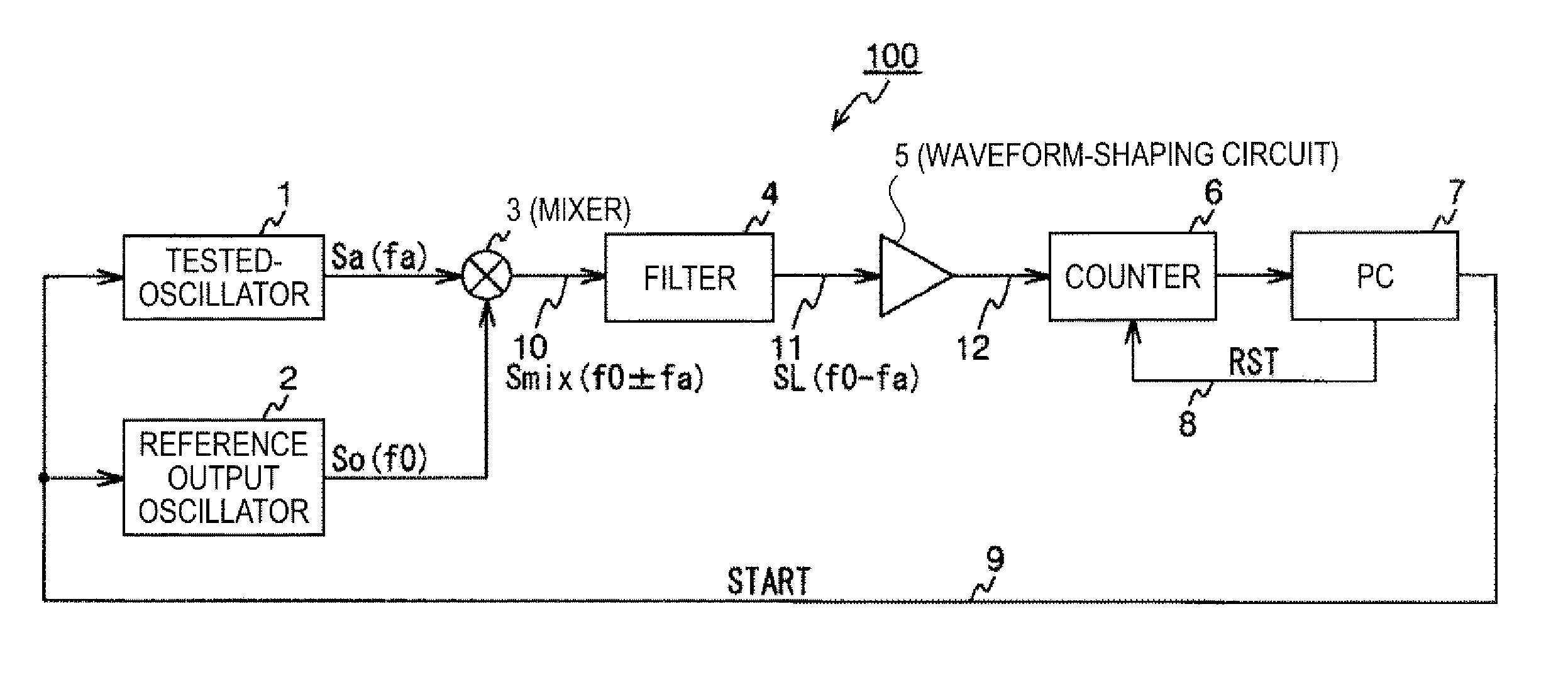
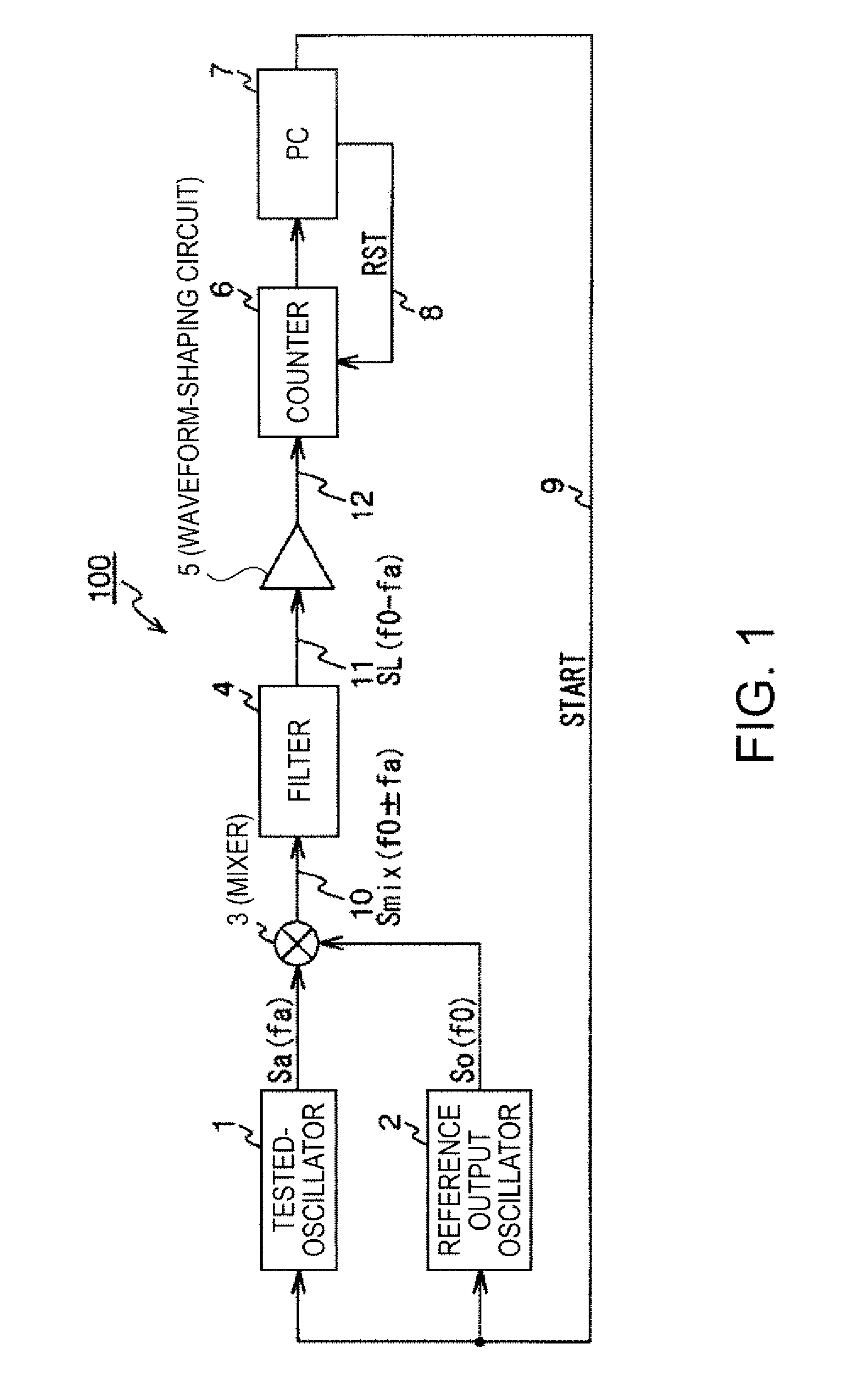
[0031]FIG. 1 is a block diagram of a frequency stability measuring apparatus 100 according to the embodiment of the invention. The frequency stability measuring apparatus 100 includes: a tested oscillator (a signal source) 1, which is to be subjected to measurement; a reference output oscillator (a reference signal output unit) 2 that outputs a reference frequency signal; a mixer 3 that mixes a signal outputted from the tested oscillator 1 with the reference frequency signal outputted from the reference output oscillator 2 and outputs a resultant signal; a filter 4 that allows a low-freque...


PUM


Abstract

A frequency stability measuring apparatus for measuring a frequency fluctuation of a signal outputted from a given signal source includes: a reference signal output unit that outputs a reference frequency signal; a mixer that mixes a signal outputted from the signal source with the reference frequency signal outputted from the reference signal output unit and outputs a resultant signal; a filter that allows a low-frequency component of the signal outputted from the mixer to pass therethrough; a waveform-shaping circuit that shapes a waveform of a signal outputted from the filter; a counter that counts a number of pulses of a signal shaped by the waveform-shaping circuit; and a control unit that calculates average frequencies of the signal outputted from the filter within respective measurement periods of a predetermined length, and calculates and outputs a standard deviation of the average frequencies calculated

Description

BACKGROUND [0001] 1. Technical Field [0002] The present invention relates to a frequency stability measuring apparatus and more specifically to a structure of a frequency stability measuring apparatus that measures a frequency stability of an oscillator under test with a high resolution. [0003] 2. Related Art [0004] A method of measuring a phase noise in order to test the frequency stability of a signal source such as an oscillator has already been known. Quadrature detection is commonly used as a method for measuring the phase noise of an oscillator that requires high frequency stability, such as an oscillator used in a communication device or the like. In the quadrature detection, an output of an oscillator under test and an output of a reference oscillator (a voltage controlled oscillator) with less noise than that of the oscillator under test are supplied to a mixer. At this time, a control voltage of a PLL circuit is controlled so that a phase difference between the oscillator ...

Claims


Application Information

Patent Timeline
Patent Type & Authority Applications(United States)
IPC IPC(8): H04B1/26
CPCG01R23/14
Inventor HATTORI, MASASHI
Owner SEIKO EPSON CORP
Why Eureka
Try Eureka