Optical disc drive

a read signals, which is applied in the field of read technology of optical disc drives, can solve the problems of reducing the signal-to-noise ratio of read signals, increasing the likelihood of read light erasing recorded marks, and increasing recording sensitivity, so as to achieve read performance equal or higher

Active Publication Date: 2011-12-27
HITACHI CONSUMER ELECTRONICS CORP +1
View PDF5 Cites 0 Cited by
  • Summary
  • Abstract
  • Description
  • Claims
  • Application Information

AI Technical Summary

Benefits of technology

[0018]The present invention has been made in view of the above circumstances, and provides a device that prevents recorded information from being erased by read light during high-frequency modulation and controls the position and shape of a read light pulse to be radiated on a recording layer.
[0044]The present invention makes it possible to provide an optical disc drive that can be more read light resistive than existing optical disc drives while maintaining read performance equal to or higher than that of the existing optical disc drives.

Problems solved by technology

This causes a problem where the SNR (signal-to-noise ratio) of a read signal is lowered.
However, particularly in the case of a rewritable disc, an increase in the recording sensitivity will increase the likelihood of causing read light to erase recorded marks.
Consequently, this causes another problem where read performance deterioration caused by a lowered SNR of a read signal cannot be readily compensated for by increasing the intensity of read light.
It means that it is difficult to simultaneously achieve the suppression of returned light noise of a laser and the prevention of the erasure of recorded information.
As is obvious from the above description, it is difficult to simultaneously maintain read performance and read light resistivity particularly when a multilayered rewritable disc is used.

Method used


Image

  • Optical disc drive
  • Optical disc drive
  • Optical disc drive

Examples


first embodiment

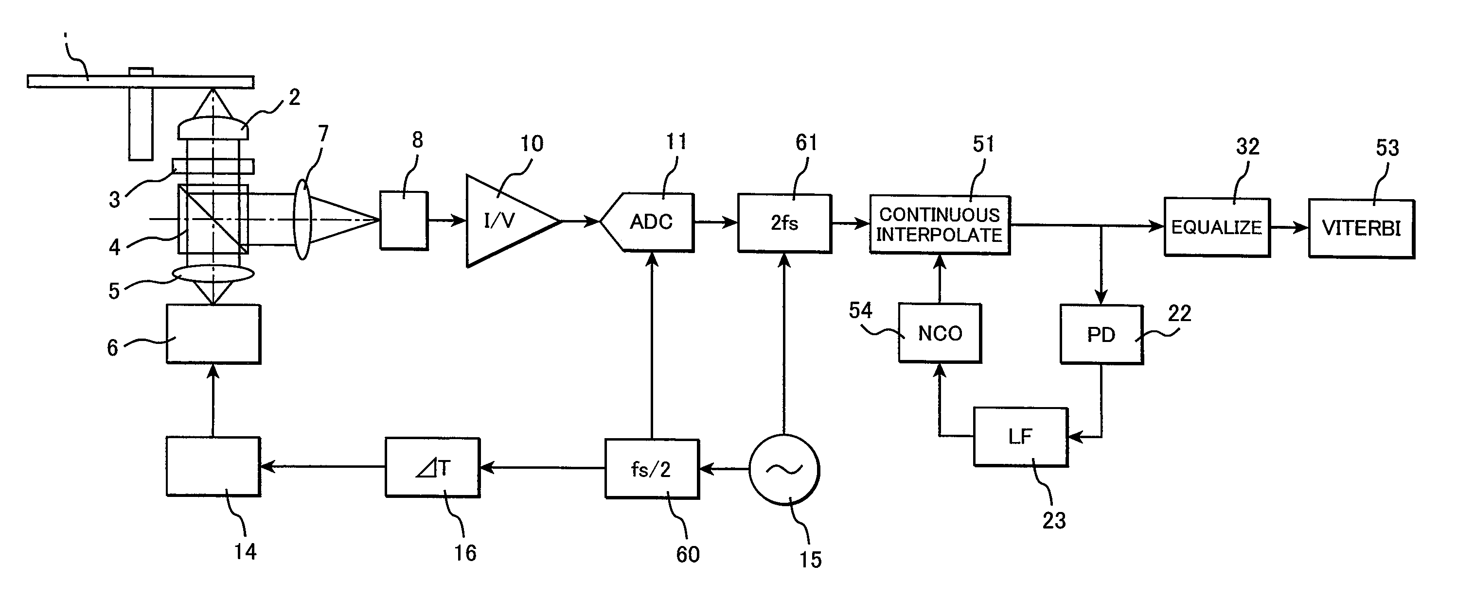
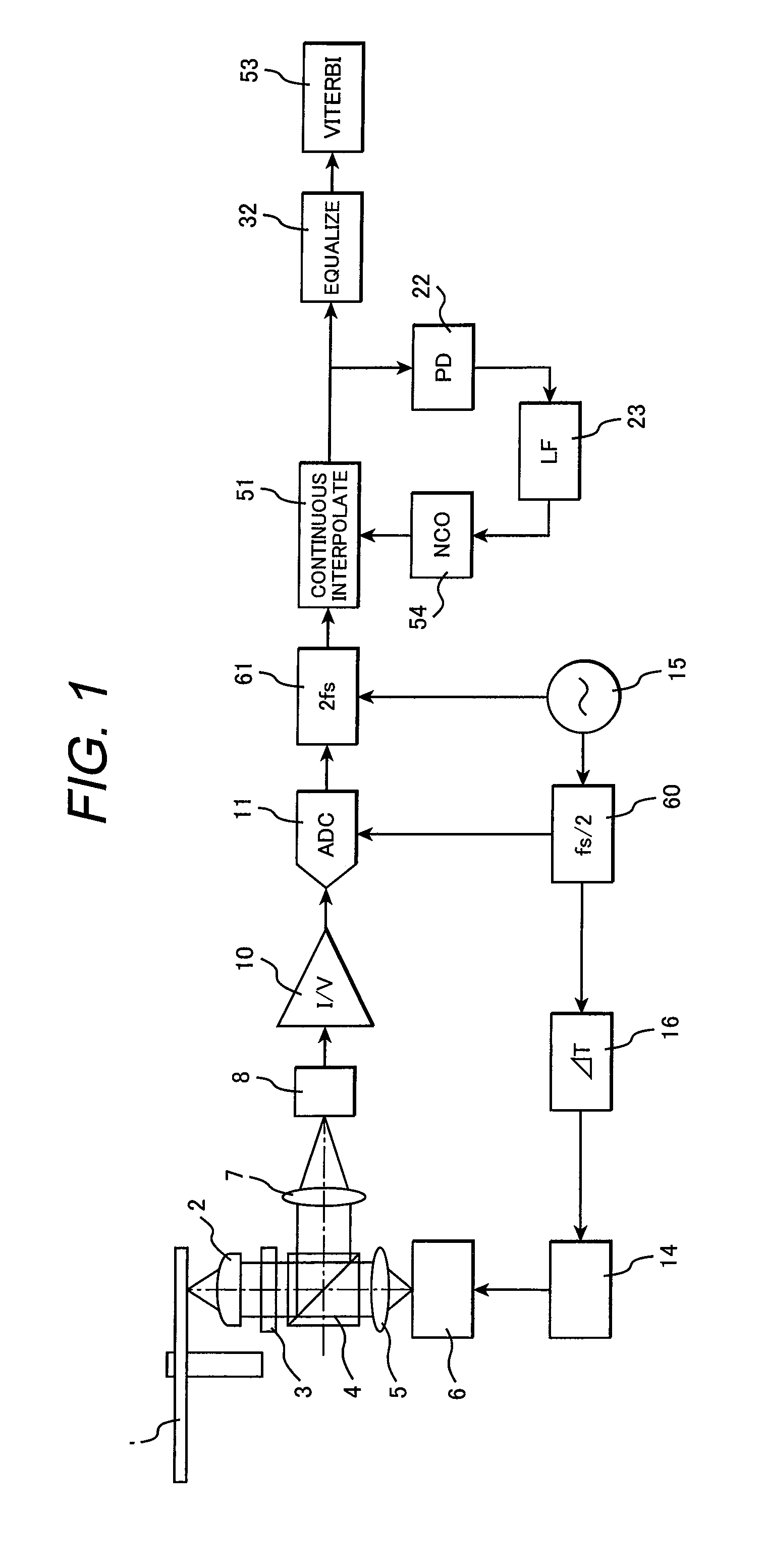
[0062]FIG. 1 shows an example of an optical disc drive according to an embodiment of the present invention. It is assumed for explanation purposes that the optical disc drive uses a BD-formatted disc having a recording capacity of 25 GB per layer. An oscillator 15 generates a clock signal having a period of τ. The value τ is close to a channel clock period T; however, τ≦T. The frequency of the clock signal is divided by half by a divider 60. The resultant clock signal then enters a laser driver 14 through a variable delay line 16. In other words, the frequency-divided clock signal is used as a carrier. The laser driver 14 synchronizes with an input oscillator output, generates a laser drive current pulse for acquiring desired average laser power, peak power, and duty, and inputs the generated laser drive current pulse into a laser diode 6. The laser driver 14 also controls a laser drive current so that the average laser output is constant.

[0063]Laser light is converted to a parallel...

second embodiment

[0075]FIG. 13 shows a second embodiment of the present invention. The second embodiment is characterized in that the position of read light pulse radiation on the recording film can be controlled. To provide such control, the present embodiment uses the voltage-controlled oscillator output of a channel PLL as a carrier to synchronize a read light pulse with a channel clock.

[0076]Referring to FIG. 13, it is assumed that the output clock of the voltage-controlled oscillator 24 is synchronized with the channel clock of a read signal. The output of the voltage-controlled oscillator enters the laser driver 14 through the variable delay line 16. The laser driver 14 synchronizes with an input voltage-controlled oscillator output, generates a laser drive current pulse for acquiring desired average laser power, peak power, and duty, and inputs the generated laser drive current pulse into the laser diode 6. The laser driver 14 also controls a laser drive current so that the average laser outp...

third embodiment

[0087]A third embodiment of the present invention will now be described with reference to FIG. 16. The configuration shown in FIG. 16 is similar to the configuration shown in FIG. 13 except that a simple laser driver 81 having no built-in write strategy is used as the laser driver. The simple laser driver is merely capable of converting an input pulse waveform to a pulse current signal for driving the laser with desired power and incapable of adjusting the pulse duty. When the simple laser driver is used, a write waveform is generated by a dedicated circuit and forwarded to the simple laser driver. In the example case shown in FIG. 16, a write waveform generation circuit 80 is used as a pulse signal source for a read light pulse. The pulse duty of the read light pulse is determined by the write waveform generation circuit 80. The output of the voltage-controlled oscillator 24 in a read PLL is used as a pulse clock for generating the read light pulse in the write waveform generation ...


PUM

PropertyMeasurementUnit
carrier frequencyaaaaaaaaaa
channel clock frequencyaaaaaaaaaa

Abstract

When a multilayered optical disc is used, the signal-to-noise ratio of a read signal is decreased as effective reflectance is extremely low due to the influence of reflection and absorption by front recording layers. Further, when a high-frequency modulation technology is used to suppress returned light noise of a laser, the erasure of recorded information is likely to occur on certain types of discs, making it difficult to simultaneously achieve the suppression of returned light noise of a laser and the prevention of the erasure of recorded information. To address the above problems, the present invention includes a section that performs a read by executing a multi-tone demodulation. The present invention also includes a section that controls the position and shape of a read light pulse to be radiated on a recording layer.

Description

CLAIM OF PRIORITY[0001]The present application claims priority from Japanese Patent Application JP 2009-230156 filed on Oct. 2, 2009, the content of which is hereby incorporated by reference into this application.BACKGROUND OF THE INVENTION[0002](1) Field of the Invention[0003]The present invention relates to a read technology for an optical disc drive, and more particularly, to a highly read light resistive optical disc drive.[0004](2) Description of the Related Art[0005]Although the scope of the present invention is not limited to Blu-ray Discs (BDs), the following description assumes that the present invention is applied to BDs. Further, technical terms used with BDs are basically used.[0006]Many of BD devices and other optical disc devices use a high-frequency modulation technology in order to suppress noise that is generated by a laser diode, which is used as their light source. This technology is disclosed in “Optics,” Vol. 14, No. 5, pp. 377-383, and well known to persons ski...

Claims


Application Information

Patent Timeline
Patent Type & Authority Patents(United States)
IPC IPC(8): G11B7/00
CPCG11B20/10009G11B20/10046G11B20/10425G11B2007/0013G11B2220/235G11B2220/2541
Inventor KIKUGAWA, ATSUSHI
Owner HITACHI CONSUMER ELECTRONICS CORP
Why Eureka
Try Eureka