Optical disc drive
- Summary
- Abstract
- Description
- Claims
- Application Information
AI Technical Summary
Benefits of technology
Problems solved by technology
Method used
Image
Examples
first embodiment
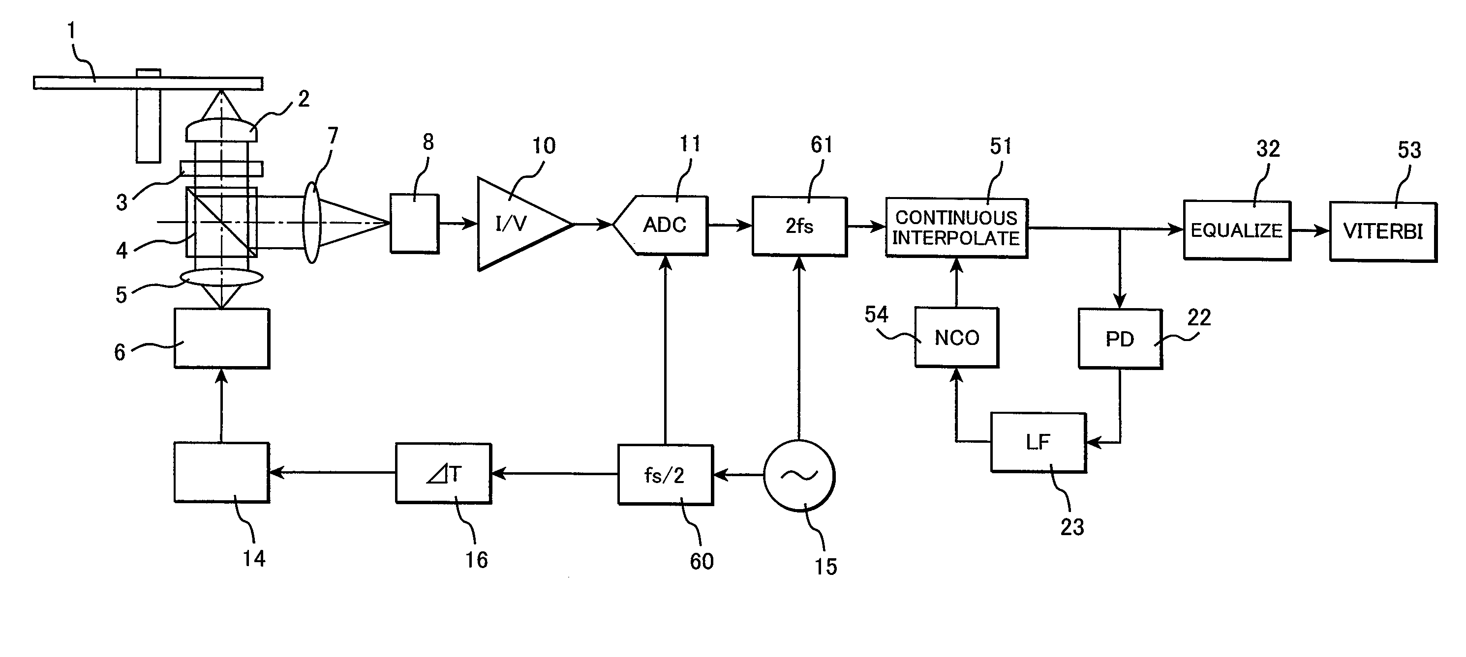
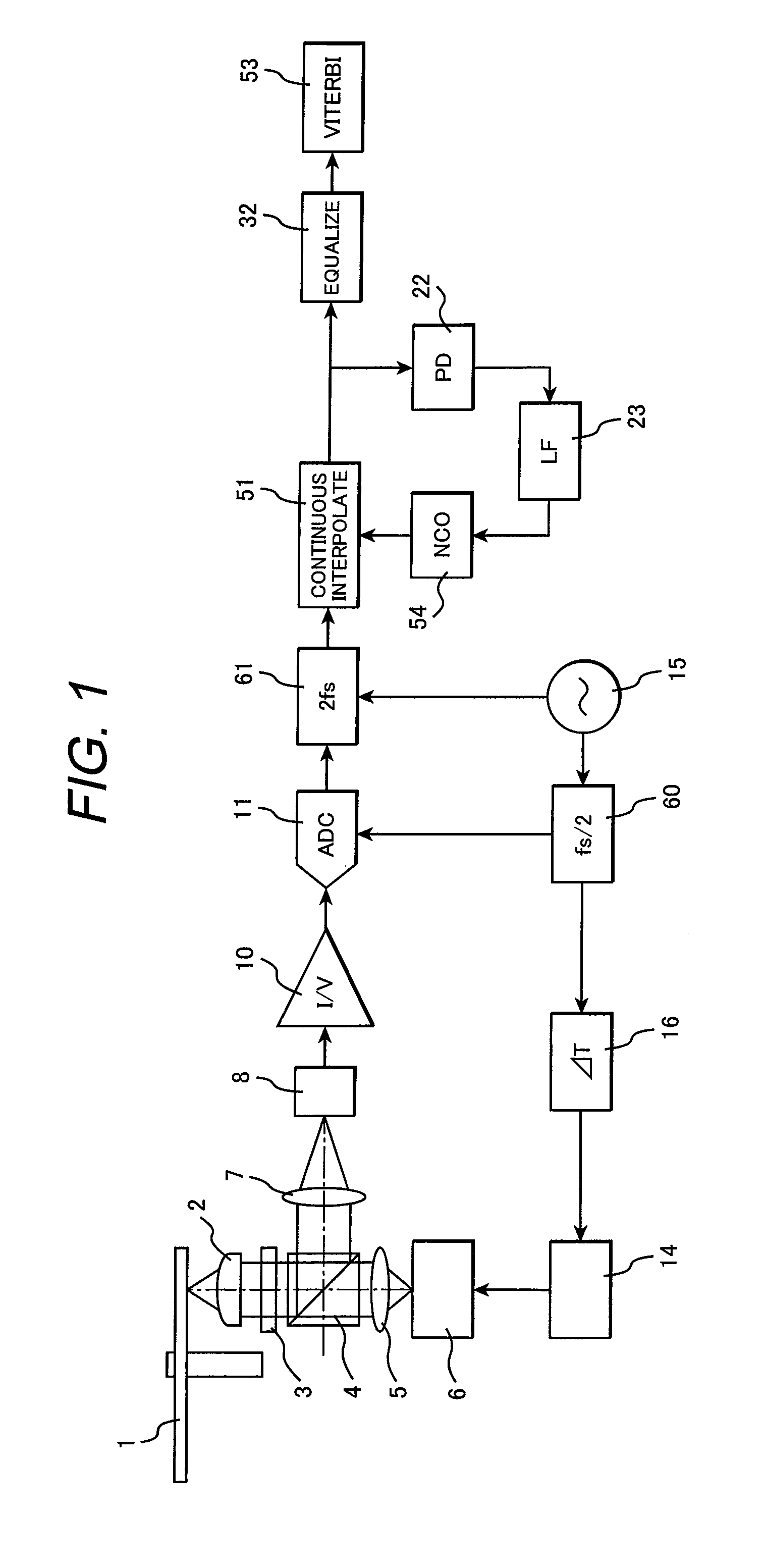
[0061]FIG. 1 shows an example of an optical disc drive according to an embodiment of the present invention. It is assumed for explanation purposes that the optical disc drive uses a BD-formatted disc having a recording capacity of 25 GB per layer. An oscillator 15 generates a clock signal having a period of τ. The value τ is close to a channel clock period T; however, τ≦T. The frequency of the clock signal is divided by half by a divider 60. The resultant clock signal then enters a laser driver 14 through a variable delay line 16. In other words, the frequency-divided clock signal is used as a carrier. The laser driver 14 synchronizes with an input oscillator output, generates a laser drive current pulse for acquiring desired average laser power, peak power, and duty, and inputs the generated laser drive current pulse into a laser diode 6. The laser driver 14 also controls a laser drive current so that the average laser output is constant.
[0062]Laser light is converted to a parallel...
second embodiment
[0074]FIG. 13 shows a second embodiment of the present invention. The second embodiment is characterized in that the position of read light pulse radiation on the recording film can be controlled. To provide such control, the present embodiment uses the voltage-controlled oscillator output of a channel PLL as a carrier to synchronize a read light pulse with a channel clock.
[0075]Referring to FIG. 13, it is assumed that the output clock of the voltage-controlled oscillator 24 is synchronized with the channel clock of a read signal. The output of the voltage-controlled oscillator enters the laser driver 14 through the variable delay line 16. The laser driver 14 synchronizes with an input voltage-controlled oscillator output, generates a laser drive current pulse for acquiring desired average laser power, peak power, and duty, and inputs the generated laser drive current pulse into the laser diode 6. The laser driver 14 also controls a laser drive current so that the average laser outp...
third embodiment
[0086]A third embodiment of the present invention will now be described with reference to FIG. 16. The configuration shown in FIG. 16 is similar to the configuration shown in FIG. 13 except that a simple laser driver 81 having no built-in write strategy is used as the laser driver. The simple laser driver is merely capable of converting an input pulse waveform to a pulse current signal for driving the laser with desired power and incapable of adjusting the pulse duty. When the simple laser driver is used, a write waveform is generated by a dedicated circuit and forwarded to the simple laser driver. In the example case shown in FIG. 16, a write waveform generation circuit 80 is used as a pulse signal source for a read light pulse. The pulse duty of the read light pulse is determined by the write waveform generation circuit 80. The output of the voltage-controlled oscillator 24 in a read PLL is used as a pulse clock for generating the read light pulse in the write waveform generation ...
PUM
 Abstract
Description
Claims
Application Information
 - R&D
- Intellectual Property
- Life Sciences
- Materials
- Tech Scout
- Unparalleled Data Quality
- Higher Quality Content
- 60% Fewer Hallucinations
Browse by: Latest US Patents, China's latest patents, Technical Efficacy Thesaurus, Application Domain, Technology Topic, Popular Technical Reports.
© 2025 PatSnap. All rights reserved.Legal|Privacy policy|Modern Slavery Act Transparency Statement|Sitemap|About US| Contact US: help@patsnap.com


