Controllable filler prefloculation using a dual polymer system

a dual-polymer system and filler technology, applied in papermaking, non-fibrous pulp addition, reinforcing agent addition, etc., can solve the problems of filler flocs, reduced finish strength, and increased difficulty in maintaining an even distribution of fillers across the three-dimensional sheet structur

Active Publication Date: 2012-01-03
NALCO CO
View PDF21 Cites 52 Cited by
  • Summary
  • Abstract
  • Description
  • Claims
  • Application Information

AI Technical Summary

Problems solved by technology

However, the substitution of cellulose fibers with fillers like calcium carbonate and clay reduces the strength of the finished sheet.
Another problem when the filler content is increased is an increased difficulty of maintaining an even distribution of fillers across the three-dimensional sheet structure.
However, filler flocs formed by a low molecular weight coagulant alone, including commonly used starch, tend to have a relatively small particle size that breaks down under the high shear forces of a paper machine.
Filler flocs formed by a single high molecular weight flocculant tend to have a broad particle size distribution that is difficult to control, and the particle size distribution gets worse at higher filler solids levels, primarily due to the poor mixing of viscous flocculent solution into the slurry.

Method used


Image

  • Controllable filler prefloculation using a dual polymer system
  • Controllable filler prefloculation using a dual polymer system
  • Controllable filler prefloculation using a dual polymer system

Examples


examples 1-7

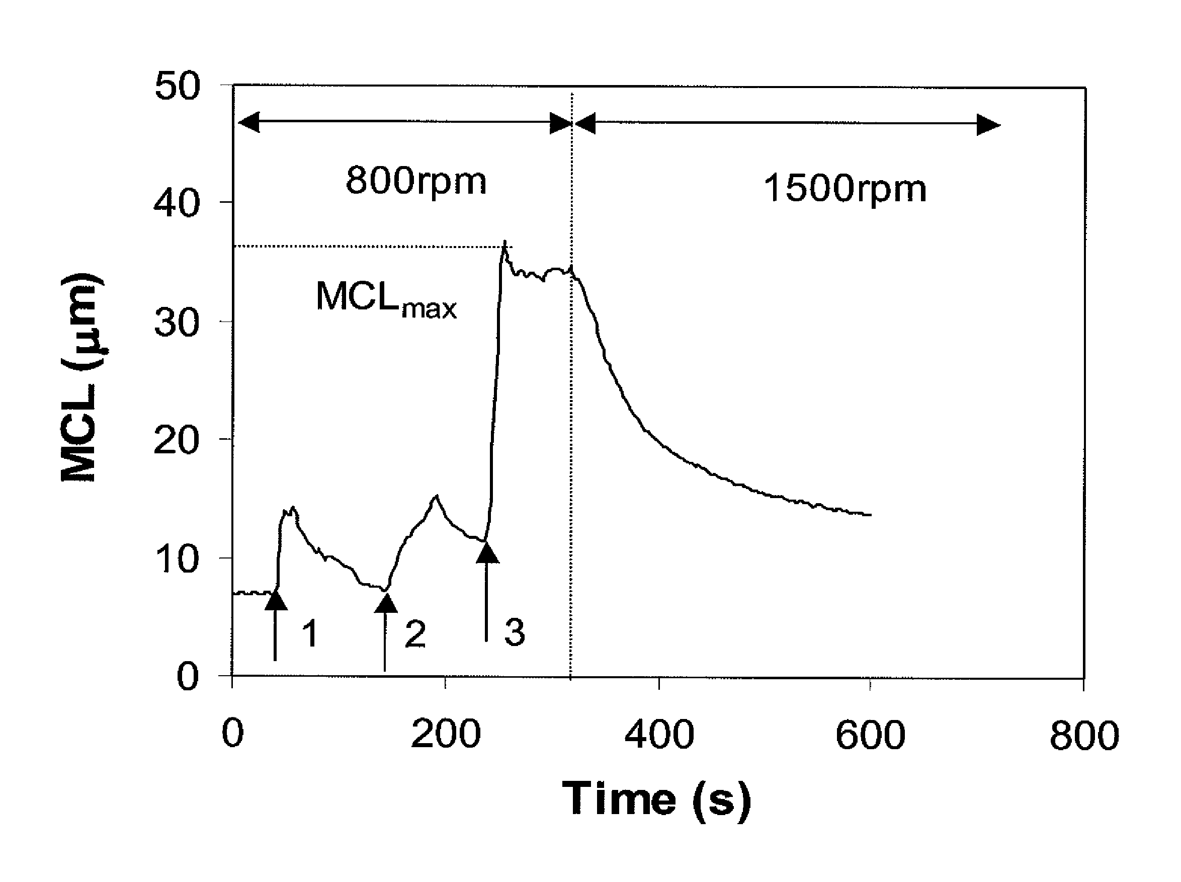
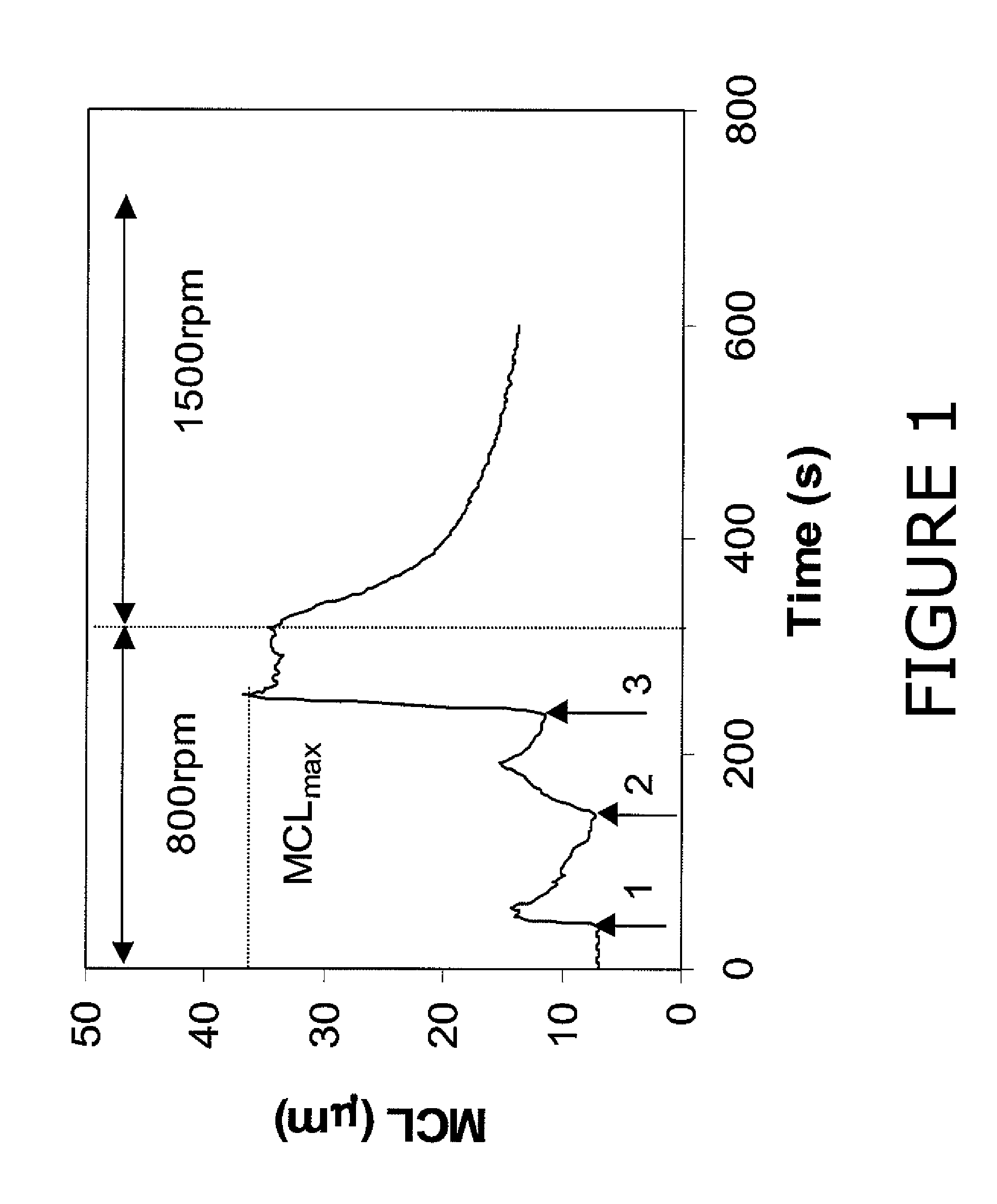
[0071]The filler used for each example was either undispersed or dispersed, scalenohedral PCC (available as Albacar HO from Specialty Minerals Inc., Bethlehem, Pa. USA). When undispersed PCC is used, the dry product was diluted to 10% solids using tap water. When dispersed PCC was used, it was obtained as 40% solids slurry and is diluted to 10% solids using tap water. The size distribution of the PCC was measured at three second intervals during flocculation using a Lasentec® S400 FBRM (Focused Beam Reflectance Measurement) probe, manufactured by Lasentec, Redmond, Wash. A description of the theory behind the operation of the FBRM can be found in U.S. Pat. No. 4,871,251. The mean chord length (MCL) of the PCC flocs is used as an overall measure of the extent of flocculation. The laser probe is inserted in a 600 mL beaker containing 300 mL of the 10% PCC slurry. The solution is stirred using an IKA RE16 stirring motor at 800 rpm for at least 30 seconds prior to the addition of floccu...

example 8

[0078]This experiment demonstrates the feasibility of using a continuous process to flocculate the PCC slurry. A batch of 18 liters of 10% solids undispersed PCC (available as Albacar HO from Specialty Minerals Inc., Bethlehem, Pa. USA) in tap water was pumped using a centrifugal pump at 7.6 L / min into a five gallon bucket. A 1.0 lb / ton active dose of 0.3% solids flocculant A solution was fed into the PCC slurry at the centrifugal pump inlet using a progressive cavity pump. The PCC was then fed into a static mixer together with 1.0 lb / ton active dose of a 0.7% solids solution of coagulant A. The size distribution of the filler flocs was measured using the Mastersizer Micro and reported in Table II. 300 mL of the resultant slurry was stirred in a beaker at 1500 rpm for 8 minutes in the same manner as in Examples 1-7. The characteristics of the filler flocs at 4 minutes and 8 minutes are listed in Tables III and IV, respectively.

example 9

[0079]The filler slurry and experimental procedure was the same as in Example 8, except that coagulant A was fed into the centrifugal pump and flocculant A was fed into the static mixer. The size characteristics of the filler flocs are listed in Tables II, III and IV.

[0080]

TABLE IPCC type, flocculating agent descriptions, and flocculatingagent doses for examples 1 through 9.Polymer 1Polymer 2MicroparticleDoseDoseDoseExPCC TypeName(lb / ton)Name(lb / ton)Name(lb / ton)1UndispersedStalok 40020NoneNone2UndispersedFlocculant A1Coagulant A1None3UndispersedCoagulant A1Flocculant A1None4UndispersedFlocculant B1Coagulant B3B25UndispersedCoagulant B3Flocculant B1B26DispersedFlocculant A1.5Coagulant A4None7DispersedCoagulant A1Flocculant A1.5None8UndispersedFlocculant A1Coagulant A1None9UndispersedCoagulant A1Flocculant A1NoneStalok 400 Cationic starch available from Tate & Lyle, Decatur, IL USAFlocculant A Anionic sodium acrylate-acrylamide copolymer flocculant with an RSV of about 32 dL / g and a c...


PUM

PropertyMeasurementUnit
median particle sizeaaaaaaaaaa
diameteraaaaaaaaaa
concentrationaaaaaaaaaa

Abstract

A method of preparing a stable dispersion of flocculated filler particles for use in papermaking processes comprises sequential addition of a first flocculating agent to an aqueous dispersion of filler particles followed by shearing of the dispersion, followed by addition of a second flocculating agent to the dispersion and further shearing of the resultant filler flocs to the desired particle size resulting in shear resistant filler flocs with a defined and controllable size distribution. In addition, a neutralizing coagulant can be added to the dispersion to partially or completely neutralize the charge of the filler before the first flocculating agent is added.

Description

CROSS-REFERENCE TO RELATED APPLICATIONS[0001]This application is a Continuation-in-part of pending U.S. patent application Ser. No. 11 / 854,044 filed on Sep. 12, 2007.STATEMENT REGARDING FEDERALLY SPONSORED RESEARCH OR DEVELOPMENT[0002]Not Applicable.BACKGROUND OF THE INVENTION[0003]This invention relates to the preflocculation of fillers used in papermaking, particularly, the production of shear resistant filler flocs with a defined and controllable size distribution at high filler solids is disclosed.[0004]Increasing the filler content in printing and writing papers is of great interest for improving product quality as well as reducing raw material and energy costs. However, the substitution of cellulose fibers with fillers like calcium carbonate and clay reduces the strength of the finished sheet. Another problem when the filler content is increased is an increased difficulty of maintaining an even distribution of fillers across the three-dimensional sheet structure. An approach t...

Claims


Application Information

Patent Timeline
Patent Type & Authority Patents(United States)
IPC IPC(8): C09C3/00C09C1/02C09C1/42
CPCD21H17/67D21H17/675D21H17/68D21H17/69D21H21/18B01J8/00D21H5/2664D21H23/04
Inventor CHENG, WEIGUOGRAY, ROSS T.
Owner NALCO CO
Why Eureka
Try Eureka