
Resin layer formation method, resin layer formation device, and disk manufacturing method

a resin layer and formation method technology, applied in the direction of electric/magnetic/electromagnetic heating, instruments, transportation and packaging, etc., can solve the problems of warp or distortion in the substrate, difficult to make the thickness of the film uniform on the entire substrate, and the outer circumference is difficult to achieve. , to achieve the effect of efficient mass production and simple procedur

Inactive Publication Date: 2012-01-03
SHIBAURA MECHATRONICS CORP
View PDF18 Cites 4 Cited by
  • Summary
  • Abstract
  • Description
  • Claims
  • Application Information

AI Technical Summary

Benefits of technology

[0010]With the foregoing in view, the present invention proposes to solve the problems of prior art, and an object thereof is to provide a resin formation method, resin formation device, disk, and disk manufacturing method for making the resin layer uniform on a substrate before lamination or on a substrate before coating using a simple procedure.

Problems solved by technology

However, in the case of the above mentioned spin coating, where adhesive is spread by centrifugal force, the thickness at the outer circumference becomes thicker than that at the inner circumference (e.g. about 10 μm), and it is difficult to make film thickness uniform on the entire substrate.
However the technology disclosed in Japanese Patent Application Laid-Open No. 2001-209980 is for making the adhesive layer uniform by laminating the substrates first, then controlling irradiation of ultraviolet and the rotation of the substrate, so if the thickness of the adhesive on the substrate before lamination is not uniform, warp or distortion is generated in the substrate during lamination, and correction in later processing becomes difficult.
Japanese Patent Application Laid-Open No. 2003-340359 is not for coating adhesive for laminating together substrates but for forming the coating layer on the surface of the substrates, so hardening is progressed by irradiating ultraviolet onto the inner circumference side, and therefore this cannot be applied to a technology for laminating together substrates.
In Japanese Patent Application Laid-Open No. 2002-63737 and No. 2004-39050, a convex portion remains on the surface of the disk, which is incompatible with uniform coating.

Method used


Image

  • Resin layer formation method, resin layer formation device, and disk manufacturing method
  • Resin layer formation method, resin layer formation device, and disk manufacturing method
  • Resin layer formation method, resin layer formation device, and disk manufacturing method

Examples


first embodiment

[Configuration of Device]

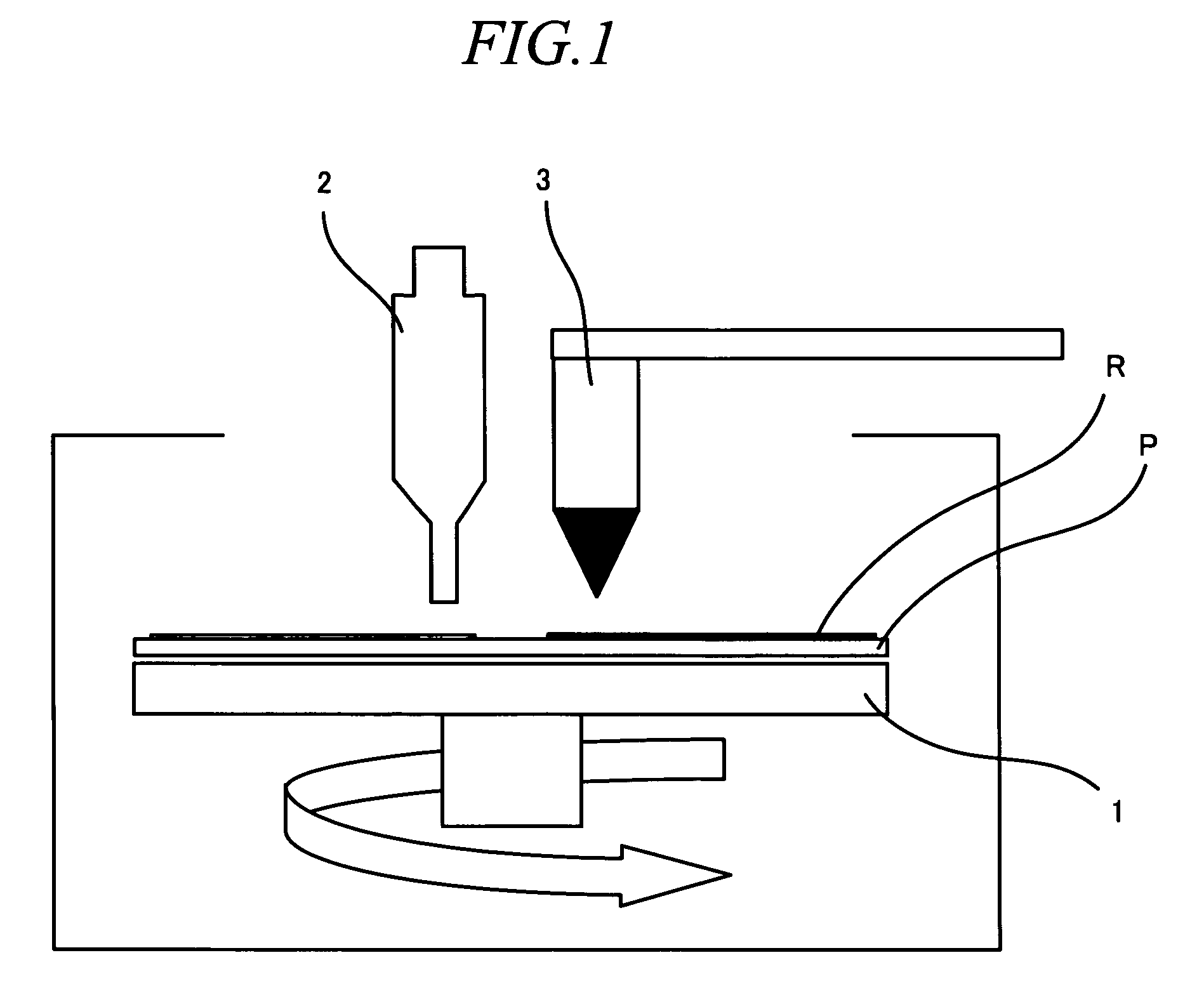
[0079]First the configuration of a resin layer formation device used for the first embodiment, (hereafter called “this device”), will be described with reference to FIG. 1. This device constitutes a part of a disk manufacturing device, and for a substrate molding device and metal film formation device which are installed in the upstream steps of this device, a laminating device of substrates and hardening device by ultraviolet radiation, which are installed in the upstream steps of this device, and a mechanism for transferring substrates between each device, various known technologies can be applied, for which description is omitted.

[0080]In other words, as shown in FIG. 1, this device has a turntable 1 on which a substrate P for a disk is mounted, an adhesive coating section 2 for coating adhesive on the substrate P, and an ultraviolet irradiation section 3 for irradiating ultraviolet onto the adhesive. The turntable 1 is a device on which a disk type subst...

example

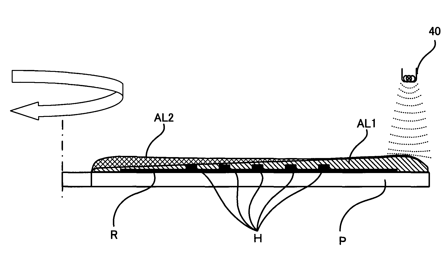
[0087]The experiment result according to an embodiment of the present invention will be described with reference to FIG. 5, FIG. 6, FIG. 9 and FIG. 10. The present experiment is on a laminated substrate for a DVD having at least two layers of recording films, that is, a semitransparent layer and a reflection layer, where the substrate on which the semitransparent layer is formed and substrate on which the total reflection layer is formed are laminated together, and the thickness of the adhesive layer was measured.

[0088]First the first adhesive layer AL1 is spread on the substrate P on which the recording film R has been formed, then the step difference section H is formed by ultraviolet irradiation, as shown in FIG. 5. The conditions of ultraviolet irradiation for forming the step difference section H are as follows. The rotation frequency of the substrate P during irradiation is 60 rpm, and the illuminance around the irradiation hole of the ultraviolet irradiation section 3 is abou...

second embodiment

[Configuration of Device]

[0093]The configuration of the resin layer formation device used for the second embodiment (hereafter called “this device”) will be described with reference to FIG. 11. This device basically has the same configuration as the above mentioned first embodiment, but the ultraviolet irradiation section 31 is placed at a height where it does not interrupt moving the substrate P (e.g. 50 to 200 mm), so that the ultraviolet UV guided from a light source 31a via an optical fiber 31b can be irradiated in a relatively wide range. Because of this, the ultraviolet UV spreads, and the irradiation range becomes about 0 to 35 mm from the center of the substrate P in the diameter direction. The irradiation range should preferably be within 50 mm in the diameter direction, but is not strictly limited to this value, or may be variable, instead of being fixed. The graph G shown at the top in FIG. 11 is an intensity distribution of the ultraviolet UV, where the abscissa indicate...


PUM

PropertyMeasurementUnit
circumferenceaaaaaaaaaa
wavelengthaaaaaaaaaa
irradiationaaaaaaaaaa

Abstract

A resin layer formation method, resin layer formation device, disk and disk manufacturing method for making a resin layer uniform on a substrate before lamination or on a substrate to be coated by a simple procedure are provided. Adhesive A is coated at the inner circumference side while rotating a substrate P at low speed, a first adhesive layer AL1 is formed on the surface of the substrate P by rotating the substrate P at high speed, a step difference section H is formed around a rotation center of the substrate P by irradiating ultraviolet on an area in the inner circumference side of the first adhesive layer AL1 and hardening the area, the adhesive A is coated at the rotation center side from the step difference section H on the substrate P, and a second adhesive layer AL2 is formed on the first adhesive layer AL1 by rotating the substrate P at high speed. The first adhesive layer AL1 and the second adhesive layer AL2 are integrated to form a uniform adhesive layer B as a whole.

Description

TECHNICAL FIELD[0001]The present invention relates to a method for forming a resin layer for adhering or coating a substrate when a flat recording medium such as an optical disk is manufactured, and more particularly to a resin layer formation method, resin layer formation device, disk, and disk manufacturing method in which accuracy of thickness of the resin layer is improved.BACKGROUND ART[0002]In optical reading type disk shape recording media, such as an optical disk and magneto-optical disk, various standards of products are on the market, including one that is read only and one on which recorded information can be overwritten. Such recording media are manufactured, in many cases, by laminating a pair of substrates with the adhesive layer in between, in order to protect the recording face formed on the substrate, or to implement high density recording by making the recording face multilayered.[0003]Such a lamination type disk is manufactured, for example, as follows. Two polyca...

Claims


Application Information

Patent Timeline
Patent Type & Authority Patents(United States)
IPC IPC(8): B05D3/12B05D3/06B05C9/08B05C11/08B05D1/40G11B7/24024G11B7/26
CPCB05C11/08B05D1/005G11B7/266Y10T156/10B05D7/56Y10T428/31504B05D1/40B05C9/08
Inventor ITO, TOMOKAZUNISHIGAKI, HISASHIKAWAKAMI, TSUKASANARITA, HARUKATAKIZAWA, YOJIHANADA, TAKUMIIWAMI, MUNENORI
Owner SHIBAURA MECHATRONICS CORP
Features
  • Generate Ideas
  • Intellectual Property
  • Life Sciences
  • Materials
  • Tech Scout
  • Unparalleled Data Quality
  • Higher Quality Content
  • 60% Fewer Hallucinations
Learn More