RNA detection method

a detection method and detection method technology, applied in the field of rna detection method, can solve the problems of difficult treatment operation steps, time-consuming and labor-intensive rt-pcr method, and achieve satisfactory performance, and achieve the effect of simple and rapid manner

Inactive Publication Date: 2012-01-03
SUMITOMO BAKELITE CO LTD
View PDF16 Cites 3 Cited by
  • Summary
  • Abstract
  • Description
  • Claims
  • Application Information

AI Technical Summary

Benefits of technology

[0017]According to the present invention, the RNA detection method capable of rapid multi-sample treatment may be provided.
[0019]From still another viewpoint, in detection of RNA from a target sample while making use of the DNA chain extension reaction, RNA may be detected and quantified in a simple and rapid manner, without including a step of decomposing RNA.

Problems solved by technology

However, the RT-PCR method is much labor-consuming in collection of cells, extraction of RNA from biological samples and purification thereof, reverse transcription reaction, PCR and gene detection, each of these steps suffers from problems of sample loss, contamination and so forth, so that the current situation is such as needing advanced skills of researchers for the purpose of stable quantification on the gene expression level.
However, use of any of these products needs time-consuming and difficult treatment operation steps.
However, the technique has failed in achieving a satisfactory performance, due to non-specific adsorption on the hydrophobic surface of plastic, raising problems in contamination of a protease or chaotropic reagent used for inactivating ribonuclease, and inactivation of reverse transcriptase and DNA synthase.[Patent Document 1] Published Japanese Translation of PCT International Publication for Patent Application No. 2003-523183[Patent Document 2] Published Japanese Translation of PCT International Publication for Patent Application No. 2002-505080[Non-Patent Document 1] Takashi Ishikawa et al., “Construction of cDNA bank from biopsy specimens for multiple gene analysis of cancer”, Clinical Chemistry, 1997, Vol. 43, No. 5, 764

Method used


Image

  • RNA detection method
  • RNA detection method
  • RNA detection method

Examples


first embodiment

[0114]FIG. 2 is a flow chart showing procedures of the RNA detection method as a first embodiment. FIG. 3A to FIG. 3C and FIG. 4A to FIG. 4D are drawings schematically showing reaction proceeded in the reaction space of the carrier, according to the flow chart shown in FIG. 2.

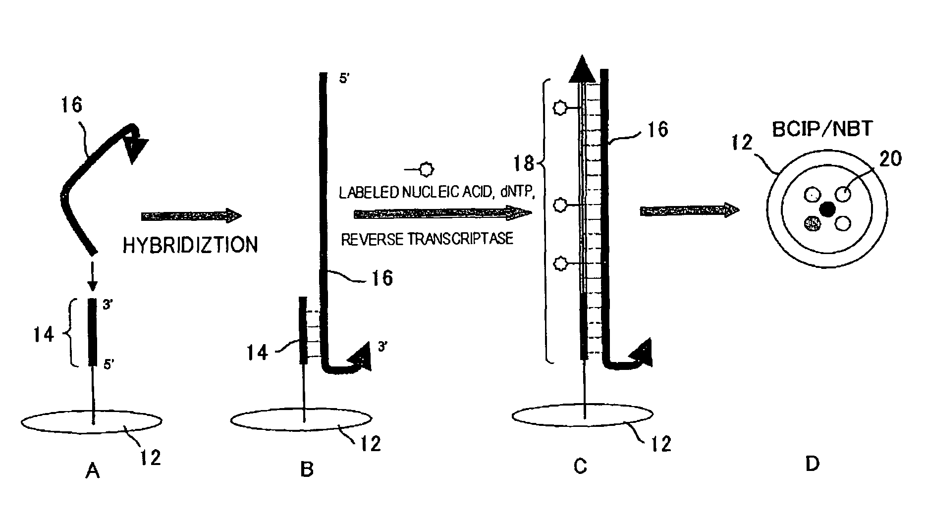
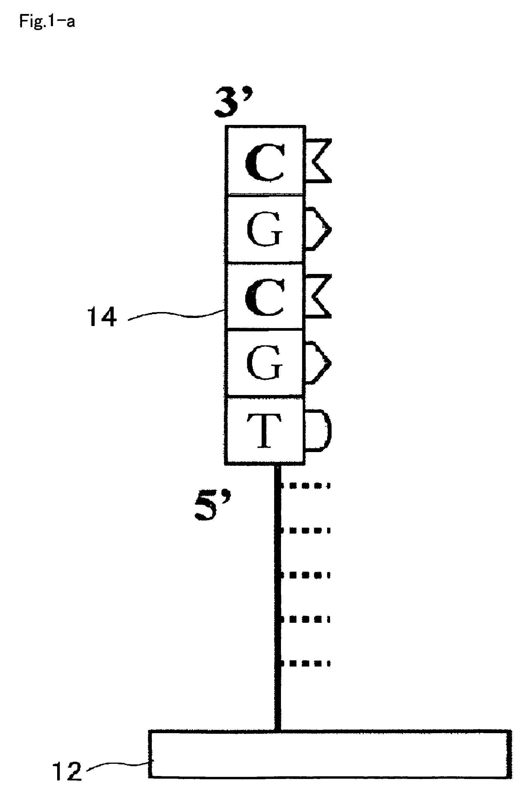
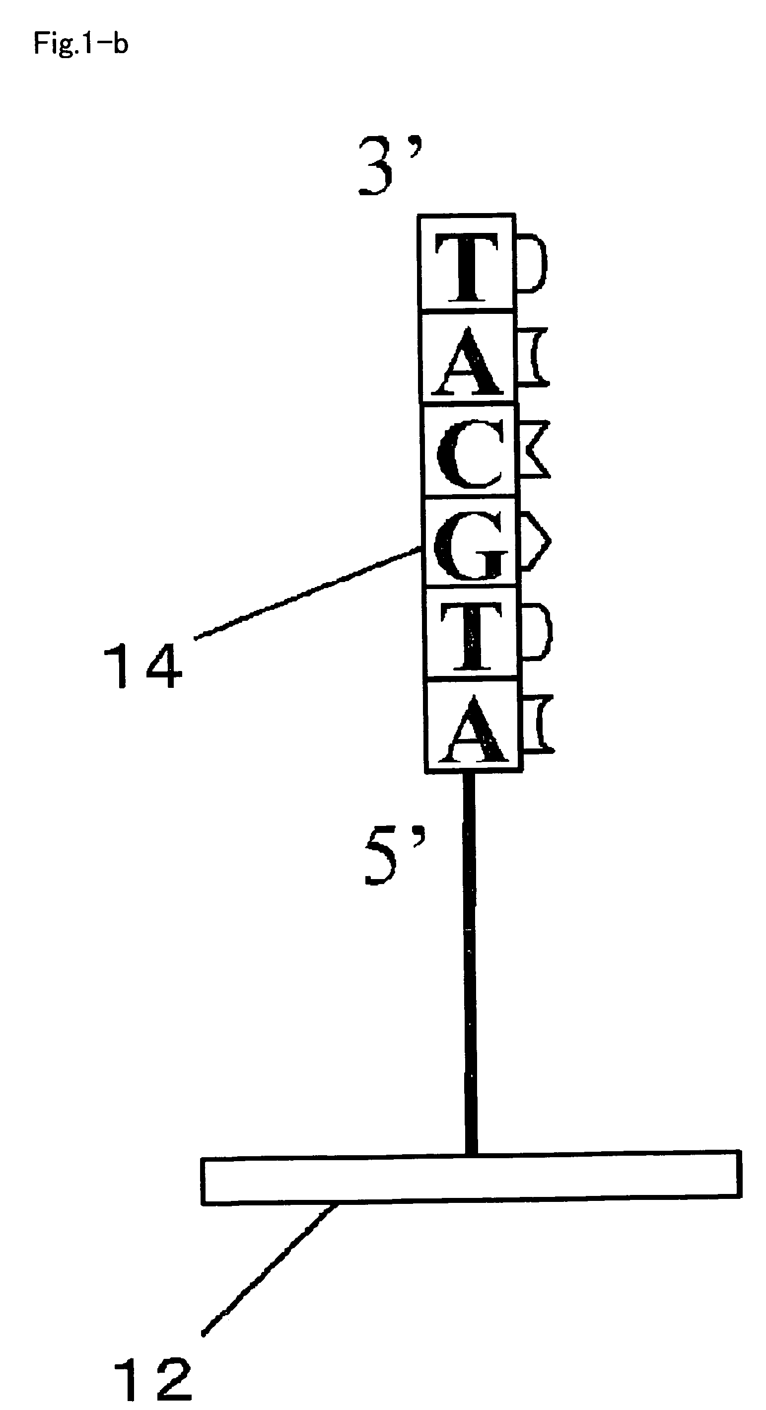
[0115]The RNA detection method includes a first step introducing a sample 22 which contains a target sample, which is typically cell lysate of target cells, an enzyme system for DNA chain extension, and nucleotide monomers into a reaction space 20 provided on the carrier 12 (substrate, for example) (step S10), and allowing DNA chain extension reaction ahead of the immobilized DNA primer (primer 14) to proceed using an RNA chain 16 contained in the target sample as a template (steps S20, S30); and a second step detecting a DNA chain 18 obtained by the extension reaction (step S50).

[0116]As shown in FIG. 2, in step S10, the sample 22 containing the cell lysate, the enzyme system for DNA chain extension, and the n...

second embodiment

[0129]FIG. 5 is a flow chart showing procedures of the RNA detection method as a second embodiment. FIG. 6A to FIG. 6D and FIG. 7A to FIG. 7E are drawing schematically showing reactions proceeded in the reaction space of the substrate, according to the flow chart shown in FIG. 5.

[0130]The RNA detection method includes a first step introducing, into the reaction space 20 provided on the carrier 12, a sample 22 containing the target sample, which is typically cell lysate of target cells, an enzyme system for DNA chain extension and nucleotide monomers (step S110), and allowing a DNA chain extension reaction to proceed ahead of the immobilized DNA primer (primer 14), while using an RNA chain 16 contained in the target sample as a template, to thereby form a cDNA chain 18 (steps S120, S130); a second step decomposing the RNA chain 16 in the reaction system 20, after the DNA chain extension reaction (step S140); a third step introducing, into the reaction system containing the cDNA chain...

third embodiment

[0142]FIG. 8 is a flow chart showing procedures of the RNA detection method as a third embodiment. FIG. 9A to FIG. 9D and FIG. 10A to FIG. 10E are drawings schematically showing the reactions proceeded in the reaction space of the carrier, according to the flow chart shown in FIG. 8.

[0143]The RNA detection method includes a first step introducing, into the reaction space 20 provided on the carrier 12, a sample 22 containing the target sample, which is typically cell lysate of target cells, an enzyme system for DNA chain extension and nucleotide monomers (step S210), and allowing a DNA chain extension reaction to proceed ahead of the immobilized DNA primer (primer 14), while using an RNA chain 16 contained in the target sample as a template, to thereby form a cDNA chain (steps S220, S230); a second step decomposing the RNA chain 16 in the reaction system containing the above-described cell lysate of the target cells, after the DNA chain extension reaction (step S240); a third step in...


PUM

PropertyMeasurementUnit
temperatureaaaaaaaaaa
pHaaaaaaaaaa

Abstract

The present invention provides an RNA detection method detecting, from a reaction system containing a target sample, a target RNA chain originated from the target sample, using a surface having on the surface thereof a polymer substance which contains a first unit having a group derived from a phosphate ester composing the hydrophilic portion of a phospholipid and a second unit having a carboxylic acid derivative group composed of an electron-attractive substitutional group bound to a carbonyl group, while being provided with at least one reaction space, the reaction space having an immobilized nucleic acid primer immobilized therein.

Description

[0001]This Application is the U.S. National Stage Application under 35 U.S.C. 371 of International Application PCT / JP / 2007 / 000592 filed Jun. 1, 2007, not in English, which claims benefit from Japanese Patent Application No. 2006-159097 filed Jun. 7, 2006, and which claims benefit from Japanese Patent Application No. 2006-258266, filed 25 Sep. 2006.TECHNICAL FIELD[0002]The present invention relates to an RNA detection method detecting an RNA chain in a sample, using a carrier having a primer DNA chain immobilized on the surface thereof.BACKGROUND ART[0003]Patent Document 1 describes a technique of allowing solid-phase amplification of a target polynucleotide to proceed, using an oligonucleotide primer immobilized on a solid-phase support. There is further disclosed that a single-strand or double-stranded DNA, and RNA may be adoptable as the target polynucleotide, and that in particular mRNA may directly be adoptable as a template for amplification as being mediated by reverse transcr...

Claims


Application Information

Patent Timeline
Patent Type & Authority Patents(United States)
IPC IPC(8): C12Q1/68C12P19/34C07H21/02C07H21/04
CPCC12Q1/6837
Inventor KINOSHITA, KENJIYOKOYAMA, KANEHISAFUJIMOTO, KENTAROYAKABE, TORUSAITO, SHINFUJIWARA, KAZUHIKO
Owner SUMITOMO BAKELITE CO LTD
Why Eureka
Try Eureka