
Method and apparatus for controlling the final feedwater temperature of a regenerative Rankine cycle using an exergetic heater system

a technology of exergetic heater and regenerative rankine cycle, which is applied in the direction of mechanical equipment, light and heating equipment, machines/engines, etc., to achieve the effects of enhancing system reliability, minimizing power loss, and high pressur

Active Publication Date: 2012-01-10
EXERGETIC SYST
View PDF6 Cites 42 Cited by
  • Summary
  • Abstract
  • Description
  • Claims
  • Application Information

AI Technical Summary

Benefits of technology

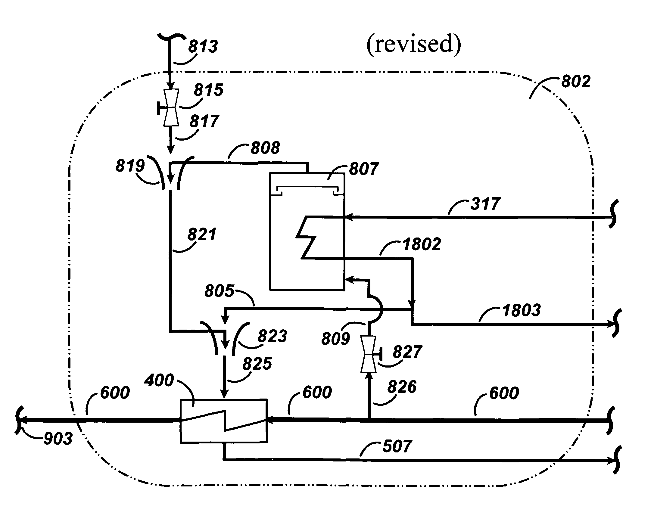
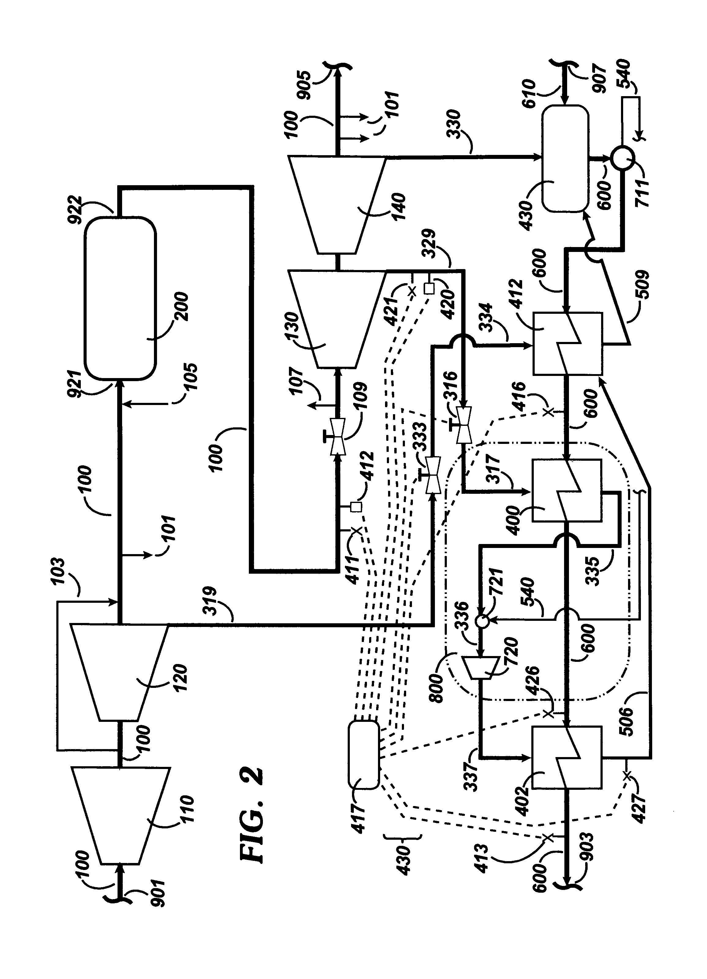
[0029]In one embodiment, the Exergetic Heater System comprises a thermocompressor and an Exergetic Heater, illustrated in FIG. 5. In this configuration of an Exergetic Heater System, the motive steam driving the thermocompressor is obtained from the steam generator. The source of motive steam may be any steam at a higher steam pressure than the pressure of the IP turbine extraction. For example, main steam may be used as motive steam. As another example, steam from the outlet of the “Primary Superheater” may be used as motive steam. The Primary Superheater is herein defined as the first working fluid heat exchanger downstream from the steam generator's drum or a point in the system where saturation is reached. Using Primary Superheater outlet steam has advantage in that it is superheated, has sufficient pressure to drive the thermocompressor, and has not consumed fuel normally required to heat the motive steam flow to main steam conditions thus minimizing power losses. The outlet from the thermocompressor is routed to the Exergetic Heater where its latent heat is transferred to the feedwater. Control of the final feedwater temperature is achieved through a control valve whose actuation adjusts the amount of steam flow being routed from the IP turbine to the Exergetic Heater System in combination with control of motive steam flow. The embodiment of FIG. 5 has the advantage of having no moving parts, thus system reliability is enhanced.
[0030]In another embodiment, the Exergetic Heater System comprises a reboiler, a thermocompressor and an Exergetic Heater, illustrated in FIG. 6. Feedwater, exiting from the last in-situ feedwater heater, is routed to a reboiler, this fluid being heated until at least saturation is reached; the resultant steam may then be combined with high pressure steam, this mixed steam is then used as motive steam in a thermocompressor to increase the pressure of IP turbine extraction steam to accomplish a heating of feedwater in the Exergetic Heater. The use of a reboiler, in combination with a thermocompressor, advantages both the high pressure associated with final feedwater, although subcooled, but then uses the vaporized feedwater to increase the IP turbine extraction pressure by acting as motive steam in a thermocompressor. If the motive steam was not vaporized, it would flash in the throat of the thermocompressor's nozzle, destroying venturi affects. In this embodiment the heating fluid for the reboiler is IP turbine extraction steam; upon exiting from the reboiler this steam (still superheated) enters the thermocompressor as supply steam. The advantage of this embodiment is that high pressure steam flow is further minimized, thus minimizing lost turbine shaft power. The embodiment of FIG. 6 employing a reboiler, thermocompressor and an Exergetic Heater assures that feedwater may be heated to its intended final temperature using less turbine steam than the embodiment illustrated in FIG. 5, provided the same source of steam is employed. The embodiment of FIG. 6 as taught herein and through FIG. 10 is the Preferred Embodiment.

Problems solved by technology

am. Further, the presence of an Exergetic Heater System divorces the power plant from inherent limitations on final feedwater temperature imposed by an un-modified regenerative Rankine cy

Method used


Image

  • Method and apparatus for controlling the final feedwater temperature of a regenerative Rankine cycle using an exergetic heater system
  • Method and apparatus for controlling the final feedwater temperature of a regenerative Rankine cycle using an exergetic heater system
  • Method and apparatus for controlling the final feedwater temperature of a regenerative Rankine cycle using an exergetic heater system

Examples


Embodiment Construction

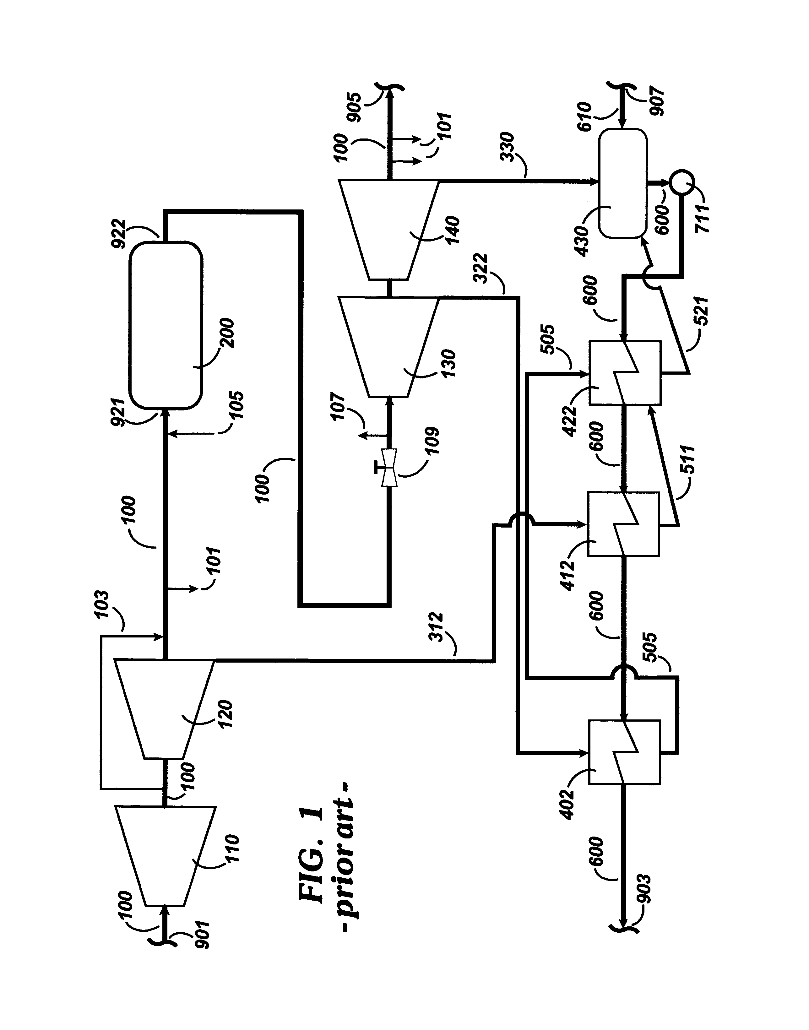
[0049]The teachings of the present invention are divided into three sections. The first section discusses the impact a degraded final feedwater temperature has on system thermal efficiency considering individual impacts on the regenerative Rankine cycle (i.e., turbine cycle efficiency) and on the steam generator (i.e., boiler efficiency). The first section contains definitions of variables. The second section discusses the impact of the IP turbine's flow passing ability and its affects on final feedwater temperature. These two sections are important as to how to properly control an Exergetic Heater System from a system's view-point. The third section teaches the implementation of the present invention, that is to correct effects on system thermal efficiency of degraded final feedwater temperature.

Final Feedwater Temperature

[0050]System thermal efficiency of a power plant employing a steam generator and a regenerative Rankine cycle may be affected by internal interface conditions (i....


PUM


Abstract

This invention relates to a method and apparatus for increasing the final feedwater temperature associated with a regenerative Rankine cycle, said cycle commonly used in thermal systems such as conventional power plants, whose steam generators are fired with a fossil fuel and whose regenerative Rankine cycle employs a reheating of the working fluid. This invention involves the placement of an Exergetic Heater System in the feedwater path of the regenerative Rankine cycle. The Exergetic Heater System conditions and heats feedwater such that the temperature of the cycle's final feedwater as it enters the steam generator has reached a desired value. The Exergetic Heater System receives its driving steam from an Intermediate Pressure turbine extraction.

Description

CROSS-REFERENCE TO RELATED APPLICATIONS[0001]This application claims benefit of priority of U.S. Provisional Application No. 61 / 001,858 filed Nov. 5, 2007 by the same inventor, the disclosure of which is incorporated herein by reference in its entirety and for all purposes. In addition, this application also claims benefit of priority of U.S. Provisional Application No. 61 / 135,261 filed Jul. 19, 2008 by the same inventor, the disclosure of which is incorporated herein by reference in its entirety and for all purposes. In addition, this application also claims benefit of priority of U.S. Provisional Application No. 61 / 135,568 filed Jul. 22, 2008 by the same inventor, the disclosure of which is incorporated herein by reference in its entirety and for all purposes. In addition, this application also claims benefit of priority of U.S. Provisional Application No. 61 / 192,055 filed Sep. 12, 2008 by the same inventor, the disclosure of which is incorporated herein by reference in its entire...

Claims


Application Information

Patent Timeline
IPC IPC(8): F01K9/00F01K13/00F01K23/06F01K7/34F01K19/10
CPCF01K3/002F01K7/34F22D1/325
Inventor LANG, FRED D.
Owner EXERGETIC SYST
Learn More