Lapping tool and method for manufacturing the same

a technology of manufacturing tool and lapping tool, which is applied in the direction of manufacturing tools, grinding devices, other chemical processes, etc., can solve the problems of difficult to use the technique described above to perform uniform lapping, abrasive grains are gripped on a surface plate, and the effect of improving the lapping efficiency

Inactive Publication Date: 2012-01-10
HITACHI LTD
View PDF14 Cites 2 Cited by
  • Summary
  • Abstract
  • Description
  • Claims
  • Application Information

AI Technical Summary

Benefits of technology

[0011]In using such conventional technique, in case of performing finest surface working, an average fixed abrasive grain size (diameter of cutting edge) of about 125 nm and a cutting edge average height of about 50 nm constitute specifications of a lapping tool, which provides substantial limits, in terms of a gripping force on a lapping tool, lapping efficiency, and surface hardness of a processed surface.
[0012]It is an object of the invention to provide a lapping method, in which a lapped part is decreased in surface roughness and damage due to working is small, in a method of manufacturing general electronic or optical devices including magnetic heads and optical connector ferrules, which are made of the composite material described above. A further object is to enable an improvement of electronic equipment, in which parts composed of the electronic or optical devices are mounted, in performance.
[0017]Accordingly, an ideal surface plate to obtain a further smooth lapped surface necessitates the use of diamond abrasive grains, which do not fall from a surface plate and are further fine, on a Sn surface plate, which is excellent in “bendability”, in order to achieve less damage to a work.
[0019]Specifically, in case of using a lapping tool, in which diamond abrasive grains embedded into a surface of the lapping tool is 100 nm or less in average diameter, under predetermined conditions of lapping, an abrasive grain drop rate is around 40% in a conventional type lapping tool having not been subjected to plasma processing, while an abrasive grain drop rate can be made less than 5% by means of optimization of conditions of plasma processing when a lapping tool of the invention is used. Lapping efficiency is improved together with reduction in grain drop rate and a work as obtained can be made further small in surface roughness together with reduction in abrasive grain size. Here, the grain drop rate means a ratio, in which diamond abrasive grains beforehand embedded into a surface plate fall, and drop abrasive grains become loose abrasive grains.
[0022]The two members are different from each other in efficiency of etching with Argon ions and in particular, a tin alloy being a base material of the plate is much etched at a bias potential of the surface plate of −100 V to −300 V. Accordingly, diamond abrasive grains project by differences in etching amount from the surface plate surface. When a work is lapped by the use of such surface plate, abrasive grains acting on the work are increased in number to lead to an improvement in lapping efficiency. In particular, an increase in lapping load makes such effect conspicuous because those abrasive grains, which are blocked by a base material of the plate to be unable to contact with the work, can also contribute to lapping.

Problems solved by technology

With magnetic heads, a member, which constitutes a reed-shaped piece described above, that is, a substrate, an insulation film, a magnetic device part, an overcoat, etc. respectively, are different in mechanical hardness, so that it is very difficult to use the technique described above to perform uniform lapping.
Also, in order to obtain a further smooth lapped surface, further small abrasive grains are used but when fixed abrasive grains are made small in grain size, a force, with which abrasive grains are gripped on a surface plate, is rapidly decreased as shown in FIG. 3, so that fixation is made difficult, drop is generated to increase loose abrasive grains, and scratch is frequently generated.

Method used


Image

  • Lapping tool and method for manufacturing the same
  • Lapping tool and method for manufacturing the same
  • Lapping tool and method for manufacturing the same

Examples


Embodiment Construction

[0041]Embodiments of the invention will be described in detail with reference to the drawings.

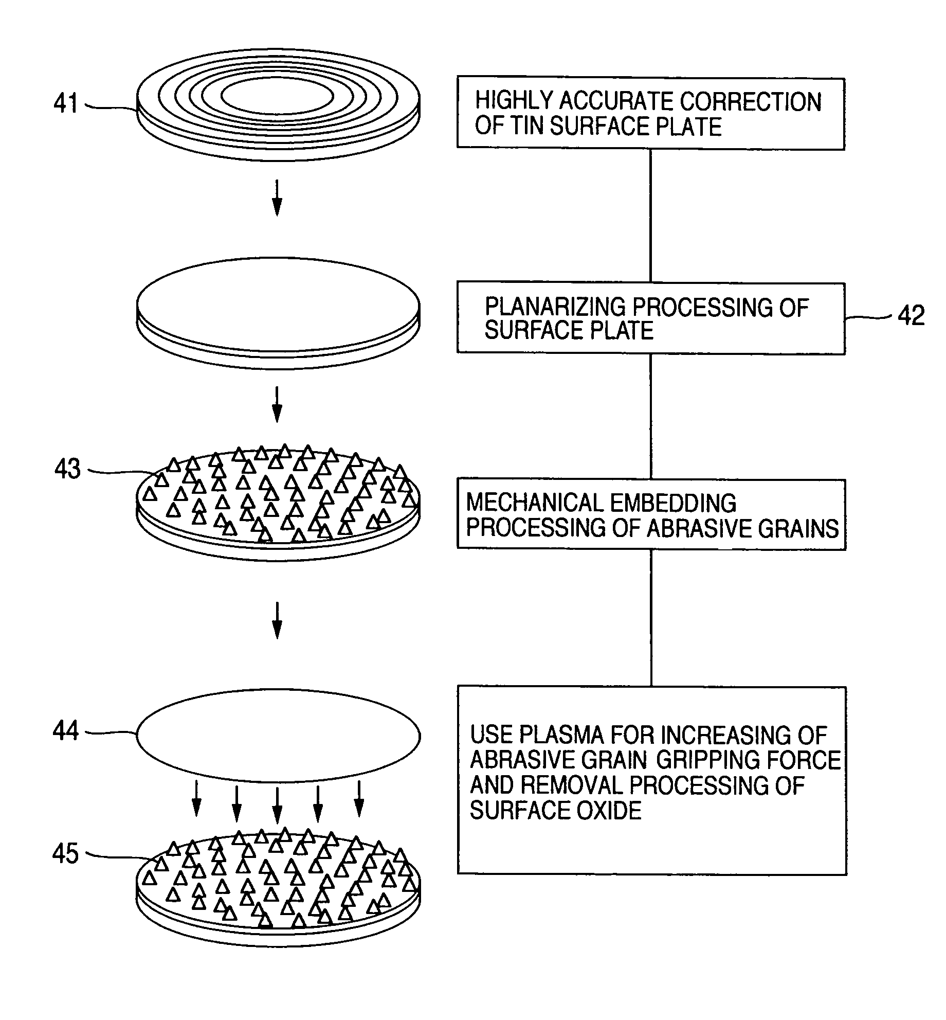
[0042]FIG. 4 is a flowchart of a method of forming a lapping tool. Specifically, a tin soft surface plate 41 having a 15 inch size (about 380 mm) was prepared and a diamond bite was used to cut a surface (referred below to as tin surface) of a tin material to perform shape correction. For a diamond bite used in correction, one having a tip end diameter of 4 mmR was used and roughness of the tin surface was made 100 nm Rmax or less. Further, in order to planarize the roughness of the whole tin surface, a lapping cloth (Supreme) manufactured by Rodel-Nitta Ltd. and a lapping slurry having alumina grains of 50 nm in average abrasive grain size dispersed in an oil were used to perform a planarization 42 to provide for an average surface roughness of 10 nm Ra, and then a washing treatment was performed.

[0043]Subsequently, the surface plate surface 41 was subjected to a treatment, in which diamon...


PUM

PropertyMeasurementUnit
sizeaaaaaaaaaa
bias potentialaaaaaaaaaa
thicknessaaaaaaaaaa

Abstract

Since structural portions of a device made of a plurality of materials are different from one another in mechanical hardness, it is very difficult to uniformly lap the structural portions. This is attributable to generation of machining recessions due to differences in lapped amount when large fixed abrasive grains are used, and generation of lapping marks caused by that the dropped abrasive grains rotate. Accordingly, in order to cope with the disadvantage, it is essential to surely grip abrasive grains of small size to a surface of a surface plate.[Solving Means]Abrasive grains are fixedly forced into a surface of a lapping tool with mechanical pressure and then the surface of the lapping tool including the abrasive grains is subjected to plasma processing, whereby an improvement in adhesion between the abrasive grains and a surface plate and reduction in the number of loose abrasive grains, which are dropped from the surface of the lapping tool, can be achieved, so that it is possible to realize lapping, in which a surface of a device made of a plurality of materials is made very plane.

Description

INCORPORATION BY REFERENCE[0001]The present application claims priority from Japanese Application JP2005-324523 filed on Nov. 9, 2005 and Japanese Application JP2006-258237 filed on Sep. 25, 2006, the content of which is hereby incorporated by reference into this application.BACKGROUND OF THE INVENTION[0002]The present invention relates to a lapping tool used for lapping of a surface of a substrate of a magnetic head used in hard disk drive, an optical connector ferrule used in optical fiber connection, etc., which is made of different materials, and a method of manufacturing the same.[0003]An improvement in areal recording density is desired in hard disk drives, and in order to attain this, a flying height of a magnetic head relative to a magnetic recording medium is needed to be further decreased from about 10 nm at present. In order to realize a decrease in flying height, it is essential that a slider surface (air bearing surface) of a magnetic head arranged in opposition to a ro...

Claims


Application Information

Patent Timeline
Patent Type & Authority Patents(United States)
IPC IPC(8): B24B1/00B05D1/12H05H1/24C23C14/00C23C14/32B24D11/00C25B11/00
CPCB24B37/12B24D18/0054
Inventor INABA, HIROSHICHIBA, HIROMUYANG, XUDONGSASAKI, SHINJIYASUI, NOBUTO
Owner HITACHI LTD
Why Eureka
Try Eureka