
Thin-film optical retarders

a thin film, optical retarder technology, applied in non-linear optics, instruments, optical elements, etc., can solve the problems of loss of birefringence, high cost of growing and polishing crystal plates, and unsatisfactory stretching of polymer films for many polarization-based projection systems. , to achieve the effect of high durability and/or stability

Active Publication Date: 2012-01-10
VIAVI SOLUTIONS INC
View PDF17 Cites 0 Cited by
  • Summary
  • Abstract
  • Description
  • Claims
  • Application Information

AI Technical Summary

Benefits of technology

The invention relates to optical retarders with in-plane birefringence introduced during a thin-film deposition process using oblique angles. The dense, form-birefringent layer is deposited with an FBAR stack to provide both A-plate and C-plate birefringence. The invention offers high durability and stability, making it suitable for high light flux polarization-based projection systems. The invention also includes a method of fabricating the optical retarder and a liquid crystal display based projection system utilizing the retarder. The technical effects of the invention include improved polarization control and compensation of residual birefringence in liquid crystal display panels.

Problems solved by technology

Unfortunately, stretched polymer films are not ideal for many polarization-based projection systems due to a lack of retardance uniformity and environmental reliability issues.
For example, with regard to the latter, the high temperature and high light flux environment provided in many microdisplay projection applications tends to make the stretched polymers relax over time, and thus lose birefringence.
In fact, the presence of any organic material, including lamination epoxy, is generally a source of reliability concerns.
While birefringent crystals are more durable and / or more stable, the cost of growing and polishing the crystal plate may be significant, especially for microdisplays having a diagonal of about one inch or greater.
While these references do provide form-birefringent thin films via oblique angle deposition, the above-described porous microstructures are not ideal for projection systems.
For example in many instances, such as when the substrate is not rotated during the deposition process, the layer thickness and hence the retardation uniformity will be poor.
In all instances, a high porosity is expected to cause reliability problems.
In addition, the large in-plane birefringence provided by the porous microstructures makes these structures particularly unsuitable for VAN-mode reflective LCD systems (e.g., VAN-mode LCoS projections TVs).

Method used


Image

  • Thin-film optical retarders
  • Thin-film optical retarders
  • Thin-film optical retarders

Examples


Embodiment Construction

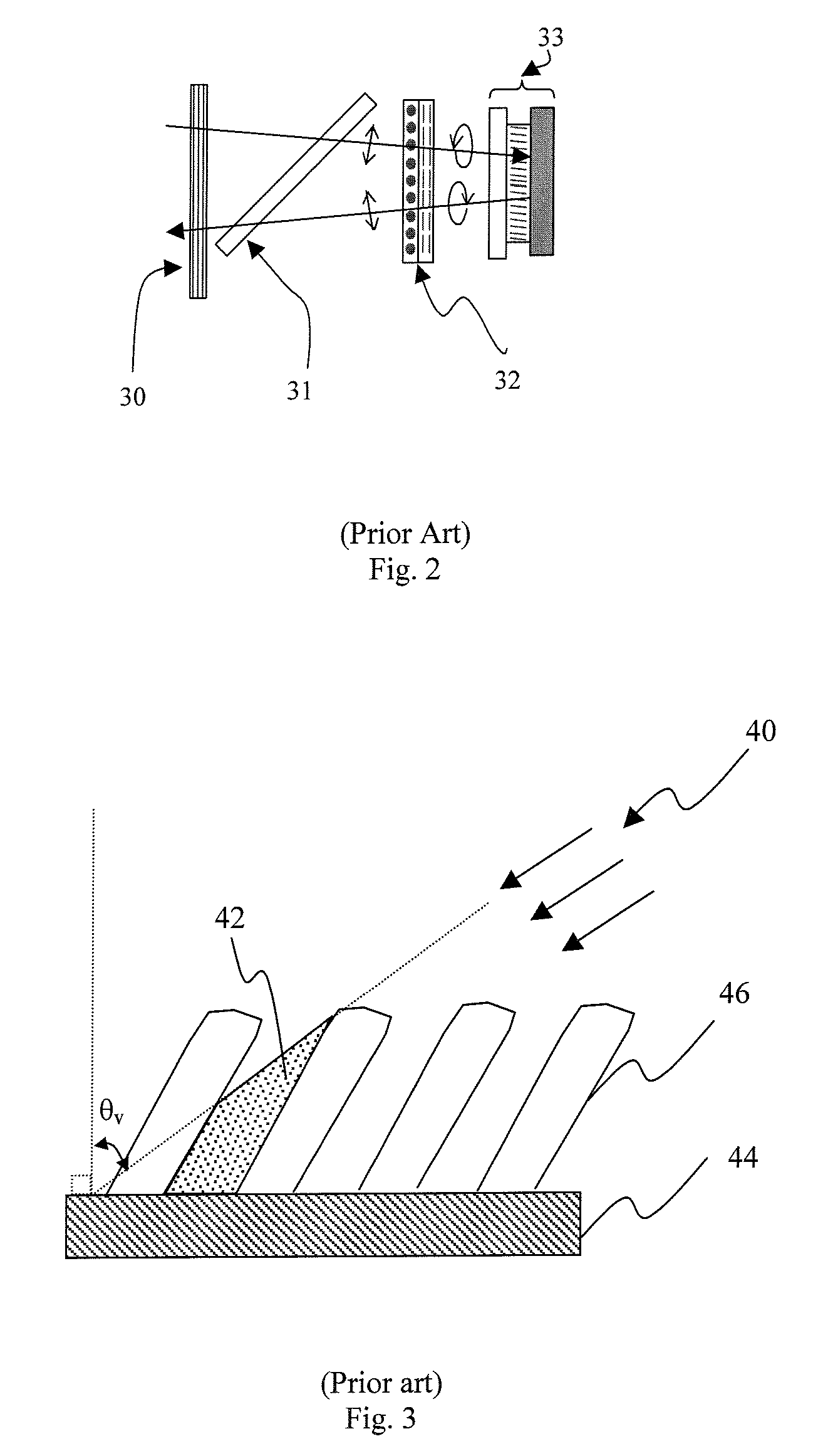
[0059]As previously discussed, birefringence in obliquely deposited thin film coatings is attributed predominantly to the columnar microstructure of the films, wherein the birefringence is dependent on the shape and direction, or tilt, of the columns. The column direction relative to the surface normal is approximately related to the angle of incidence of the coating material arriving at the substrate by the tangent rule

tan ψ=0.5 tan θv   (1)

where ψ is the angle of the column relative to the substrate normal, and θv is the deposition angle relative to the substrate normal. The column angle typically is the direction of the z-axis of the birefringent material. This relationship has been experimentally verified for oxide materials such as TiO2, Ta2O5 and ZrO2. In contrast, SiO2 has been found to form mostly isotropic films, whereas films of Ta2O5 are more closely approximated by

tan ψ=0.322 tan θv   (2)

[0060]The experimental relationship between the in-plane (i.e., normal incidence) bi...


PUM

PropertyMeasurementUnit
wavelengthaaaaaaaaaa
deposition angleaaaaaaaaaa

Abstract

An oblique angle deposition is used to provide an A-plate optical retarder having at least one dense, form-birefringent layer. According to one embodiment, the dense, form-birefringent layer(s) are deposited as part of an FBAR stack to provide an all-dielectric full-function A / −C-plate trim retarder for LCD birefringence compensation. Advantageously, the dense structure of the full-function A / −C-plate trim retarder offers high durability and / or stability, thus making it well suited for providing polarization compensation in high light flux polarization-based projection systems.

Description

CROSS-REFERENCE TO RELATED APPLICATIONS[0001]This application claims priority from U.S. Provisional Application No. 60 / 742,940 filed Dec. 6, 2005, which is hereby incorporated by reference.MICROFICHE APPENDIX[0002]Not Applicable.TECHNICAL FIELD[0003]The present application relates generally to polarization control, and in particular, to thin-film optical retarders for providing birefringence in polarization-sensitive optical systems.BACKGROUND OF THE INVENTION[0004]Optical retarders are used to alter the relative phase of polarized light passing therethrough, and thus, are well suited for use in applications where control over the polarization is required. In addition to inducing ¼- and ½-wave retardations to control the polarization of light, optical retarders are also used to provide polarization compensation for other optical components in a system. For example, optical retarder compensators are used to introduce a phase delay in incident light to correct for phase differences be...

Claims


Application Information

Patent Timeline
Patent Type & Authority Patents(United States)
IPC IPC(8): G02F1/1335G02F1/13
CPCG02B5/3083G03B21/14H04N9/3105H04N9/3167H04N9/3197G02B1/115G03B21/2073G03B33/12
Inventor HENDRIX, KAREN D.TAN, KIM L.HULSE, CHARLES A.SARGENT, ROBERT B.KLINGER, ROBERT E.
Owner VIAVI SOLUTIONS INC
Learn More