Methods to fabricate a photoactive substrate suitable for shaped glass structures

a technology of photoactive substrate and shaped glass, which is applied in the direction of glass tempering apparatus, manufacturing tools, instruments, etc., can solve the problem that the process can produce very high anisotropic-etch ratios, and achieve the effect of reducing the overall diameter of the micropost and low wall slop

Active Publication Date: 2012-01-17
3D GLASS SOLUTIONS INC
View PDF15 Cites 38 Cited by
  • Summary
  • Abstract
  • Description
  • Claims
  • Application Information

AI Technical Summary

Benefits of technology

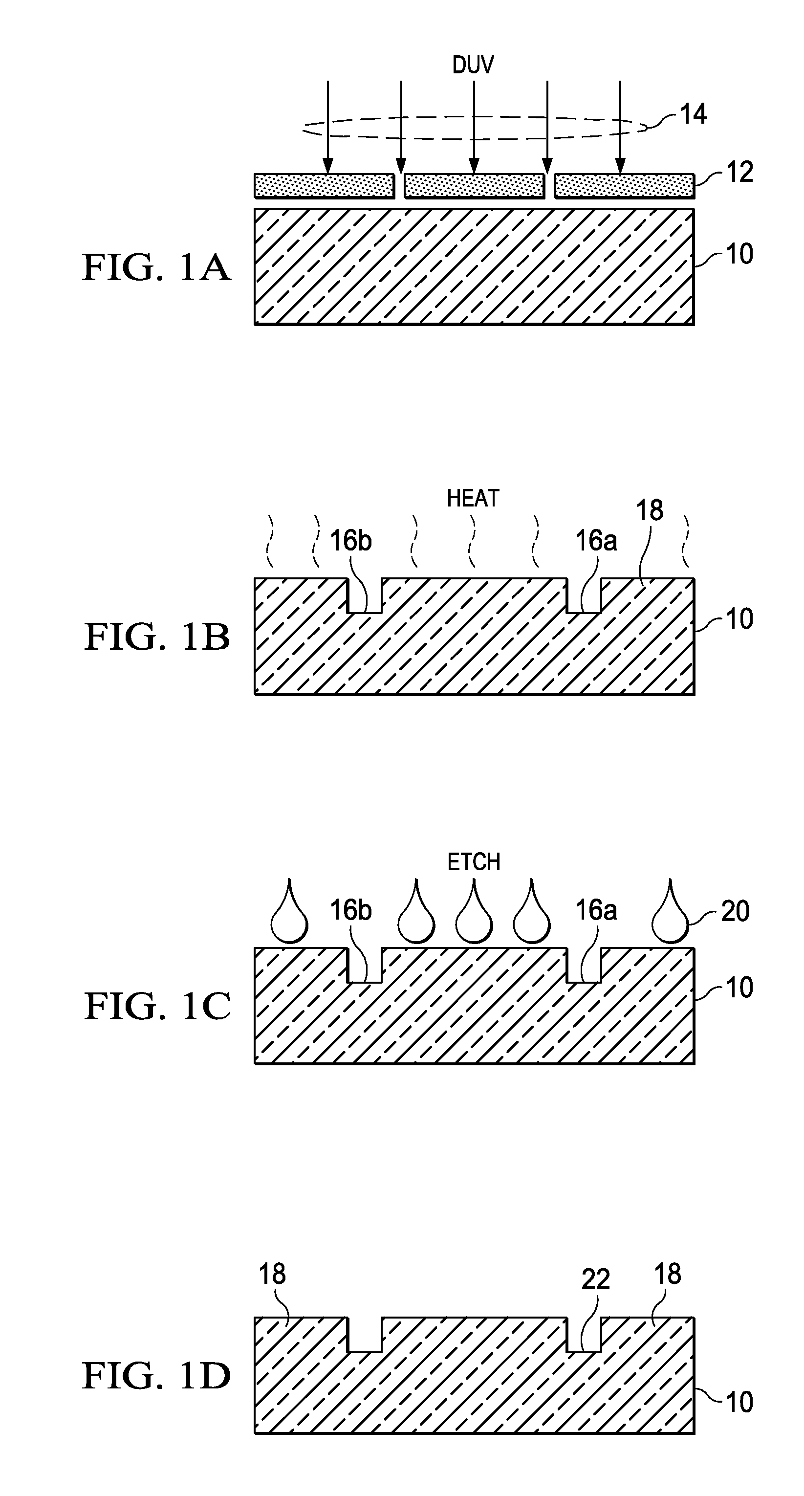
[0005]The present invention is directed to a method to do glass micromachining with etch ratios of 30:1 or more using a mid-ultraviolet flood exposure system and potentially 40:1 or more (preferably 50:1 or more) using a laser-based exposure system, to produce high-precision structures, and to produce, by using ultraviolet light, a change in the index of refraction for the pattern and development of high-precision light guiding structures. Thus, for example, with nearly vertical wall slopes on both the inside and outside diameters of hollow photostructured microneedles only minor wall-thickness variation from tip to base would occur. In addition, microposts, which are non-hollow microneedles, may be micromachined to possess a low wall slope, enabling a decrease in the overall micropost diameter. Likewise, micro-lenses can be shaped with precisely controlled horizontal variations and have only minor vertical variation.
[0010]All embodiments are essentially germanium-free. In some embodiments, Sb2O3 or As2O3 is added (e.g. at least 0.3 weight % Sb2O3 or As2O3) to help control the oxidation state of the composition. In some preferred embodiments, at least 0.75 weight % B2O3 is included, and in others at least 1.25 weight % B2O3 is included. In some preferred embodiments, at least 0.003% Au2O is included in addition to at least 0.003 weight % Ag2O. In some embodiments, a combination of CaO and / or ZnO is added up to 18 weight %. In some embodiments, up to 10 weight % MgO is added. In some embodiments, up to 18 weight % lead oxide is added. Up to 5 weight %, Fe2O3, may be added to make the material paramagnetic and iron (II) and iron (III) may be added as a quenching agent to reduce autofluorescence of the glass.
[0015]Preferably, the shaped glass structure contains at least one of, a micro-optic lens, a micro-optic micro-post, a micro-channel, or micro-ridge micro-optic waveguide. The micro-ridge, optical waveguide may be formed by etching away exposed glass to leave a glass micro-ridge such that light is guided by the micro-ridge. The micro-ridge may be formed using a layer of photosensitive glass overlying a layer of non-photosensitive glass of lower index of refraction than the photosensitive glass, to substantially prevent micro-ridge-guided light from leaving the bottom of the micro-ridge in at least one portion of the micro-ridge (e.g. bottom vias may be etched in the non-photosensitive glass to allow light coupling to a light guide on a lower level).
[0021]The glass structure may be patterned to create exposed regions of higher index of refraction surrounded by areas of lower index of refraction, such that light is substantially contained within the higher index of refraction material. Conversely, the patterned glass structure may be patterned to create exposed regions of higher index of refraction surrounding areas of lower index of refraction, such that light is substantially contained within the lower index of refraction material. Either way, exposing our glass with such ultraviolet light can raise index of refraction of the glass and the changed index of refraction may used to direct, manipulate, or process photons. Thus in some cases, etching of the glass is not necessary to direct light within such a patterned glass structure.
[0023]In some embodiments, a surface-smoothing acid containing at least one of nitric acid is used to dissolve surface metallic silver and / or hydrochloric acid is used to dissolve surface cerium metal is used during or after the HF etch, to reduce surface roughness of at least one micro-optic device in the shaped glass structure, such that light transmission through surfaces of a micro-optic device is increased. The final patterned glass structure may also be annealed near its glass transition temperature to smooth out etched side walls.

Problems solved by technology

Furthermore, unlike expensive dry-etching processes used in silicon-semiconductor-type processes, this process can produce very high anisotropic-etch ratios with relatively inexpensive wet etching.

Method used


Image

  • Methods to fabricate a photoactive substrate suitable for shaped glass structures
  • Methods to fabricate a photoactive substrate suitable for shaped glass structures
  • Methods to fabricate a photoactive substrate suitable for shaped glass structures

Examples


Embodiment Construction

[0039]While the making and using of various embodiments of the present invention are discussed in detail below, it should be appreciated that the present invention provides many applicable inventive concepts that can be embodied in a wide variety of specific contexts. The specific embodiments discussed herein are merely illustrative of specific ways to make and use the invention and do not restrict the scope of the invention.

[0040]To facilitate the understanding of this invention, a number of terms are defined below. Terms defined herein have meanings as commonly understood by a person of ordinary skill in the areas relevant to the present invention. Terms such as “a”, “an” and “the” are not intended to refer to only a singular entity, but include the general class of which a specific example may be used for illustration. The terminology herein is used to describe specific embodiments of the invention, but their usage does not delimit the invention, except as outlined in the claims....


PUM

PropertyMeasurementUnit
temperatureaaaaaaaaaa
weight %aaaaaaaaaa

Abstract

This invention provides an inexpensive and rapid method for fabricating a high-anisotropic-etch ratio, shaped glass structures using a novel photosensitive glass composition. Structures of the photosensitive glass may include micro-channels, micro-optics, microposts, or arrays of hollow micro-needles. Furthermore, such shaped glass structures can be used to form a negative mold for casting the shape in other materials.

Description

CROSS-REFERENCE TO RELATED APPLICATIONS[0001]This application claims priority to U.S. Provisional Application Ser. No. 60 / 908,631, filed Mar. 28, 2007, and 60 / 910,257, filed Apr. 5, 2007, the contents of each of which are incorporated by reference herein in their entirety.FIELD OF THE INVENTION[0002]The present invention relates to a method to fabricate a shaped glass structure with a high-anisotropic-etch ratio and, in particular, a method to fabricate a shaped glass structure with a high-anisotropic-etch ratio using a novel photosensitive glass composition.BACKGROUND OF THE INVENTION[0003]Photosensitive glass structures have been suggested for a number of micromachining and microfabrication processes such as inkjet printer heads, electrodes for high quality head phones, micro-lens arrays, positioning devices, and hollow microneedle arrays being developed for transdermal drug delivery and the withdrawal of body fluids for biomedical and other applications. Unfortunately, silicon mi...

Claims


Application Information

Patent Timeline
Patent Type & Authority Patents(United States)
IPC IPC(8): C03B32/02
CPCC03C3/095C03C4/04C03C15/00C03C23/007C03C3/108C03C23/002Y10T428/24479C03C2218/34B32B3/10C03C25/62
Inventor FLEMMING, JEB H.BUCKLEY, COLIN T.SCHMIDT, CARRIE
Owner 3D GLASS SOLUTIONS INC
Why Eureka
Try Eureka