Optical correlation apparatus and method

a technology of optical correlation and apparatus, applied in the direction of instruments, measurement devices, electromagnetic wave reradiation, etc., can solve the problems of reducing the ability of the system to discriminate between close objects, affecting the accuracy of the signal, so as to improve the signal to noise ratio, the effect of low cross-correlation and high autocorrelation

Inactive Publication Date: 2012-01-17
INSTRO PREC
View PDF15 Cites 1 Cited by
  • Summary
  • Abstract
  • Description
  • Claims
  • Application Information

AI Technical Summary

Benefits of technology

[0029]By selecting from a number of modulation signals based on the digital sequence a number of different signals can be provided which have low cross-correlation between different signals and yet have a high autocorrelation allowing faint reflections to be picked up. This can be done without the need to generate different maximal length sequences, which can be technically quite difficult.
[0030]In practical systems, synchronous integration is used to improve the signal to noise ratio. This is often done using a circular buffer of the same length as the number of clock cycles of the modulation signal. The modulation signal is repeated, and the received signal added to the circular buffer for each peak. Whilst random noise produces a received signal that is not correlated with the modulation signal, reflections tend to be correlated with the modulation signal, and so produce correlation peaks.
[0031]The modified digital sequences still produce good performance with synchronous integration without requiring complex systems to generate a vast number of different maximum length sequences.

Problems solved by technology

A problem that may occur in vehicle applications, as well as other applications, is the possibility of interference between similar systems.
However, the use of different oversampling factors results in significantly different lengths of modulation signal which complicates the design of the signal processing. and larger oversampling factors reduce the ability of the system to discriminate between close objects.

Method used


Image

  • Optical correlation apparatus and method
  • Optical correlation apparatus and method
  • Optical correlation apparatus and method

Examples


Embodiment Construction

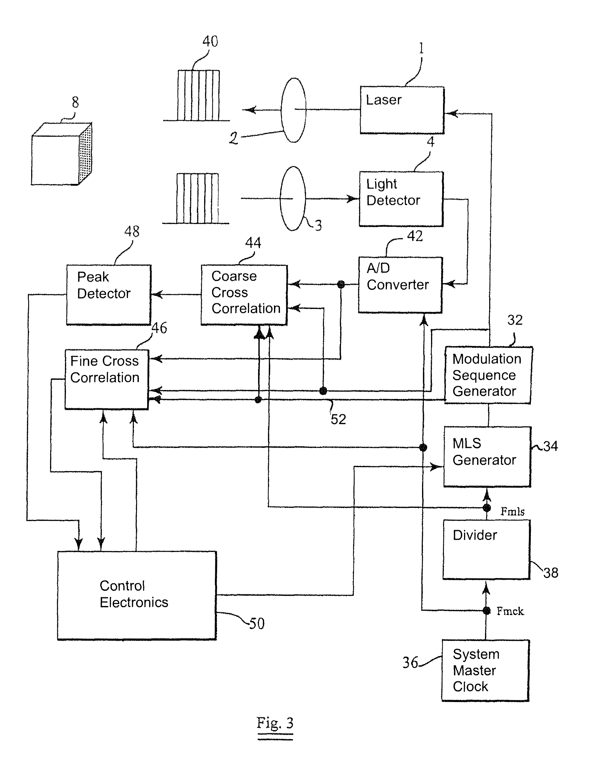
[0051]One example of how optical distance measurement equipment based on the MLS technique can be improved by using the invention is illustrated in FIG. 3. The system is incorporated in a vehicle.

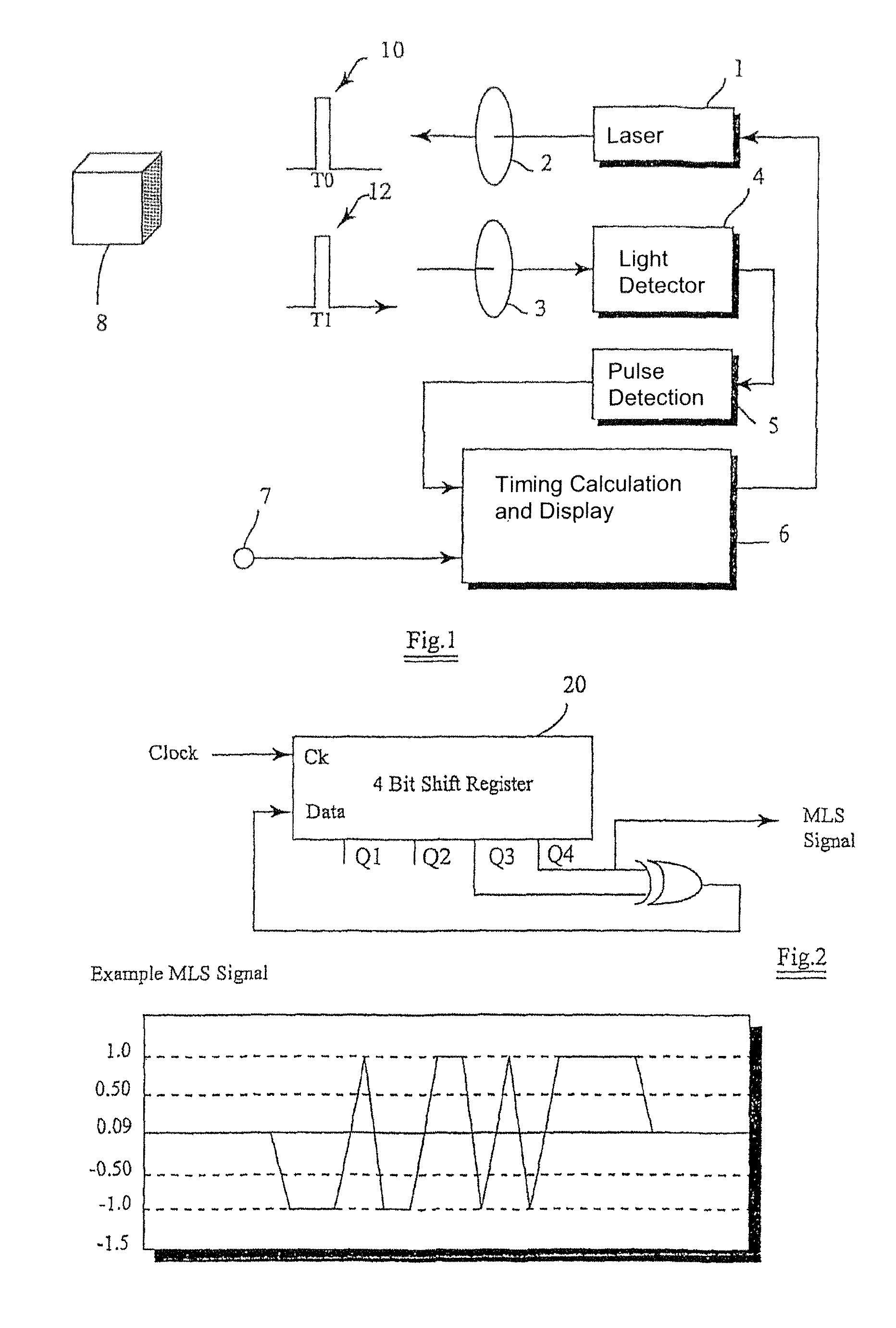
[0052]A maximal length sequence generator 34 is connected to master clock generator 36 through divider 38. This divider 38 generates a MLS frequency that is a fraction of the master clock frequency, and the maximal length sequence generator generates a maximal length sequence.

[0053]The maximal length sequence generator is connected in turn to modulation sequence generator 32 that modifies the maximal length sequence to be one of a number of modulation sequences. The modulation sequence generator is connected to laser 1 which generates an optical signal through transmission optics 2.

[0054]Receiving optics 3 receives light and focuses it onto light sensitive detector 4, which in turn feeds the signal to analogue to digital converter 42. The digital output is fed to both a coarse and a fine cr...


PUM


Abstract

Optical correlators are discussed, suitable for in-vehicle distance measurement. The correlators use modulation sequences based on maximal length sequences. A number of different modulation sequences are obtained by generator (32) from a single maximal length sequence, either by adding a variable number of cycles to the end of the maximal length sequence or by starting the maximal length sequence at different points in the sequence.

Description

FIELD OF THE INVENTION[0001]The invention relates to apparatus and a method for an optical correlation measurement and in particular but not exclusively to a method and apparatus for optical correlation for automotive applications.DESCRIPTION OF RELATED ART[0002]Various optical detection devices are available for measuring the distance to a remote object. Such devices may be used, for example, in vehicle collision avoidance systems.[0003]One common approach to measuring distance to a far object is to measure the time of flight of a pulse of light from the measuring system to the far object and back again, and then to calculate the distance to the far object based upon the speed of light. Systems employing this method commonly employ a laser to generate the light pulse and so are known generically as “laser range finders” (LRF's) or “light detection and ranging” (LiDAR) systems. Typical applications are the measurement of altitude, target range or distance for survey applications in ...

Claims


Application Information

Patent Timeline
Patent Type & Authority Patents(United States)
IPC IPC(8): H04B1/00G01S17/32G01S7/4911G01S7/4915G01S7/493G01S13/02G01S13/32
CPCG01S7/023G01S7/4911G01S7/493G01S17/32G01S7/4915G01S13/325G01S7/0235G01S17/26
Inventor MORCOM, CHRISTOPHER JOHN
Owner INSTRO PREC
Why Eureka
Try Eureka