Purge gas concentration estimation apparatus

a technology of concentration estimation and purge gas, which is applied in mechanical devices, machines/engines, instruments, etc., can solve the problems of response delay, and inability to accurately detect the amount of purge gas

Inactive Publication Date: 2012-01-24
MAHLE FILTER SYST JAPAN CORP
View PDF16 Cites 13 Cited by
  • Summary
  • Abstract
  • Description
  • Claims
  • Application Information

AI Technical Summary

Benefits of technology

[0010]It is therefore an object of the present invention to provide a purge gas concentration estimation apparatus which is capable of estimating the purge gas concentration instantly and accurately.

Problems solved by technology

In Japanese Patent Document 1, however, since the degree of saturation of the canister is calculated on the basis of the canister inside temperature and the exhaust air-fuel ratio after the evaporated fuel purged from the canister is burnt in the engine, there could arise a detection delay (a response delay) or an error caused by an effect of temperature change occurring by the purge.
However, with regard to the adsorbent (activated carbon) that fills the canister, in a case of low boiling point gas such as gasoline vapor, since an ambient gas concentration is saturated under a condition in which an adsorption state is beyond a certain level, an accurate adsorption state cannot be detected by the concentration sensor.
For this reason, there is a problem that the fuel amount in the purge gas cannot accurately be detected.

Method used


Image

  • Purge gas concentration estimation apparatus
  • Purge gas concentration estimation apparatus
  • Purge gas concentration estimation apparatus

Examples


first embodiment

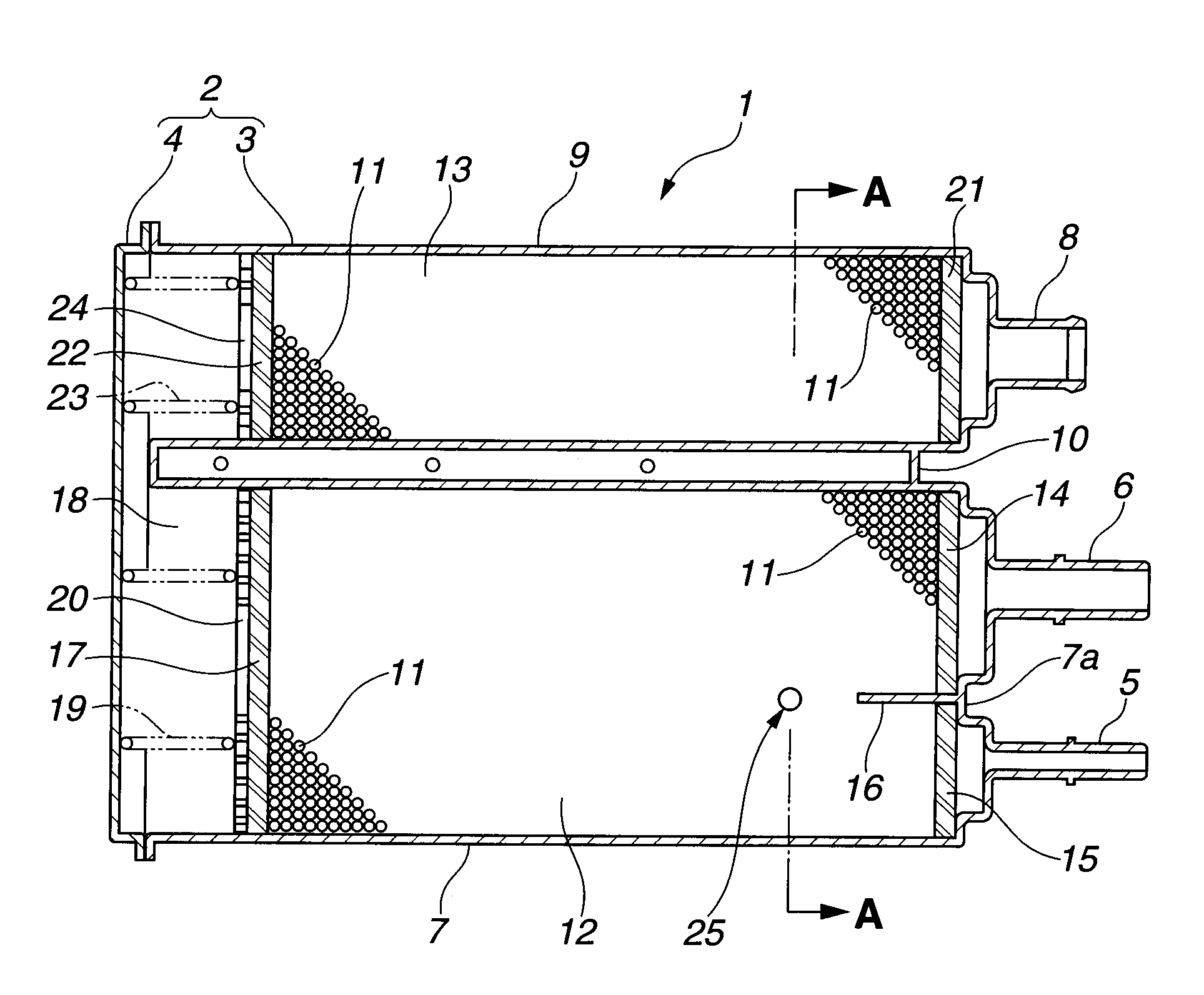
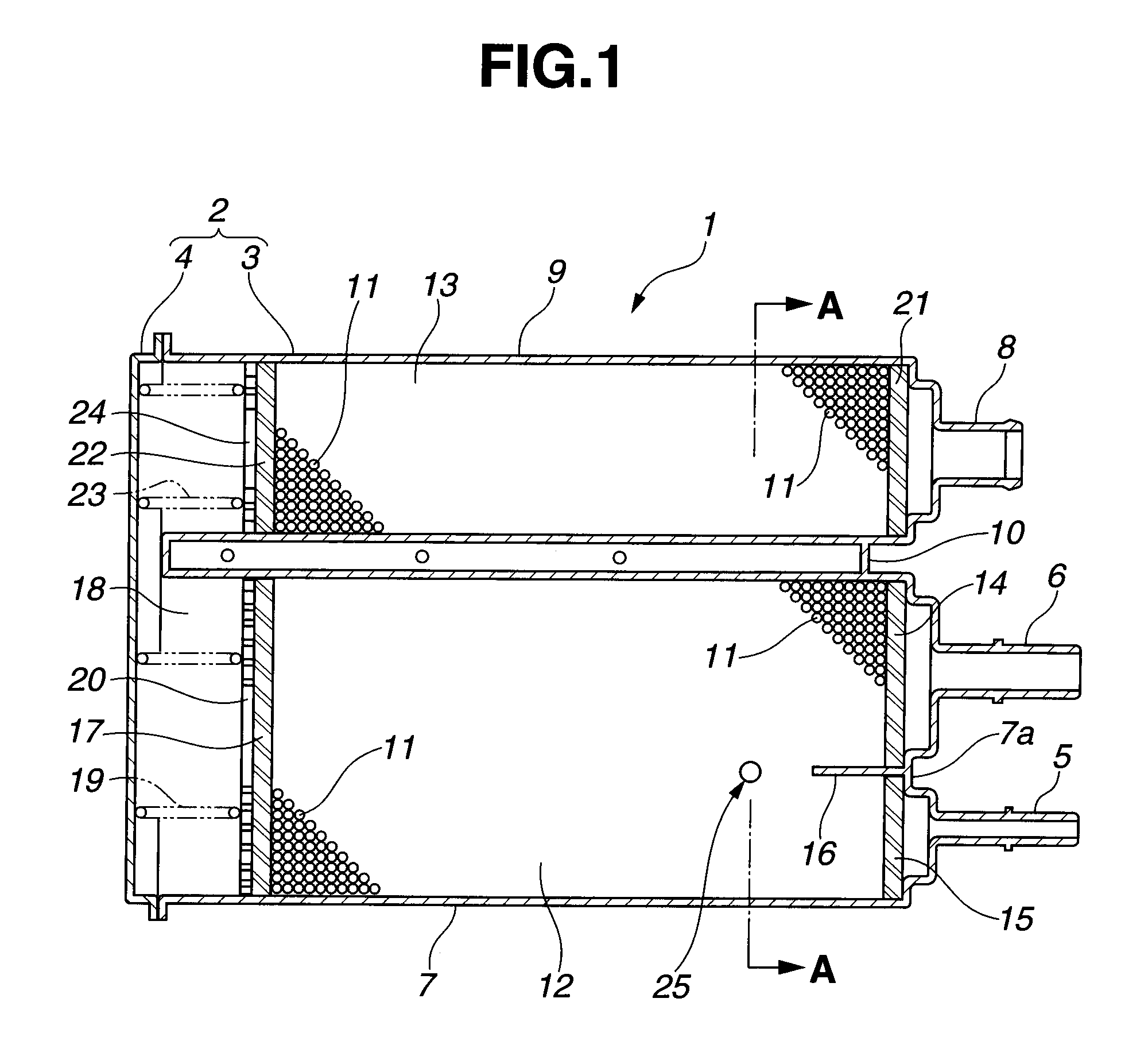
[0040]As explained above, in the first embodiment, by detecting the heat capacity of an inside of the casing 2, namely the heat capacity of the activated carbon 11, the HC adsorption amount of the activated carbon 11 can be directly detected. With this detection, by using the HC adsorption amount (adsorption amount of the evaporated fuel) of the activated carbon 11, which is detected through the current energization before the engine start, irrespective of the HC adsorption amount of the adsorbent, it is possible to instantly and accurately estimate the purge gas concentration that is the fuel concentration in the purge gas upon execution of the purge.

[0041]Further, by employing the hot-wire sensor 25, the HC adsorption amount in the canister 1 can be directly detected with a less expensive system.

[0042]Moreover, by placing the hot-wire sensor 25 near or close to the purge port 5 in the canister 1, i.e. at the position where the adsorption amount of the evaporated fuel is large in t...

second embodiment

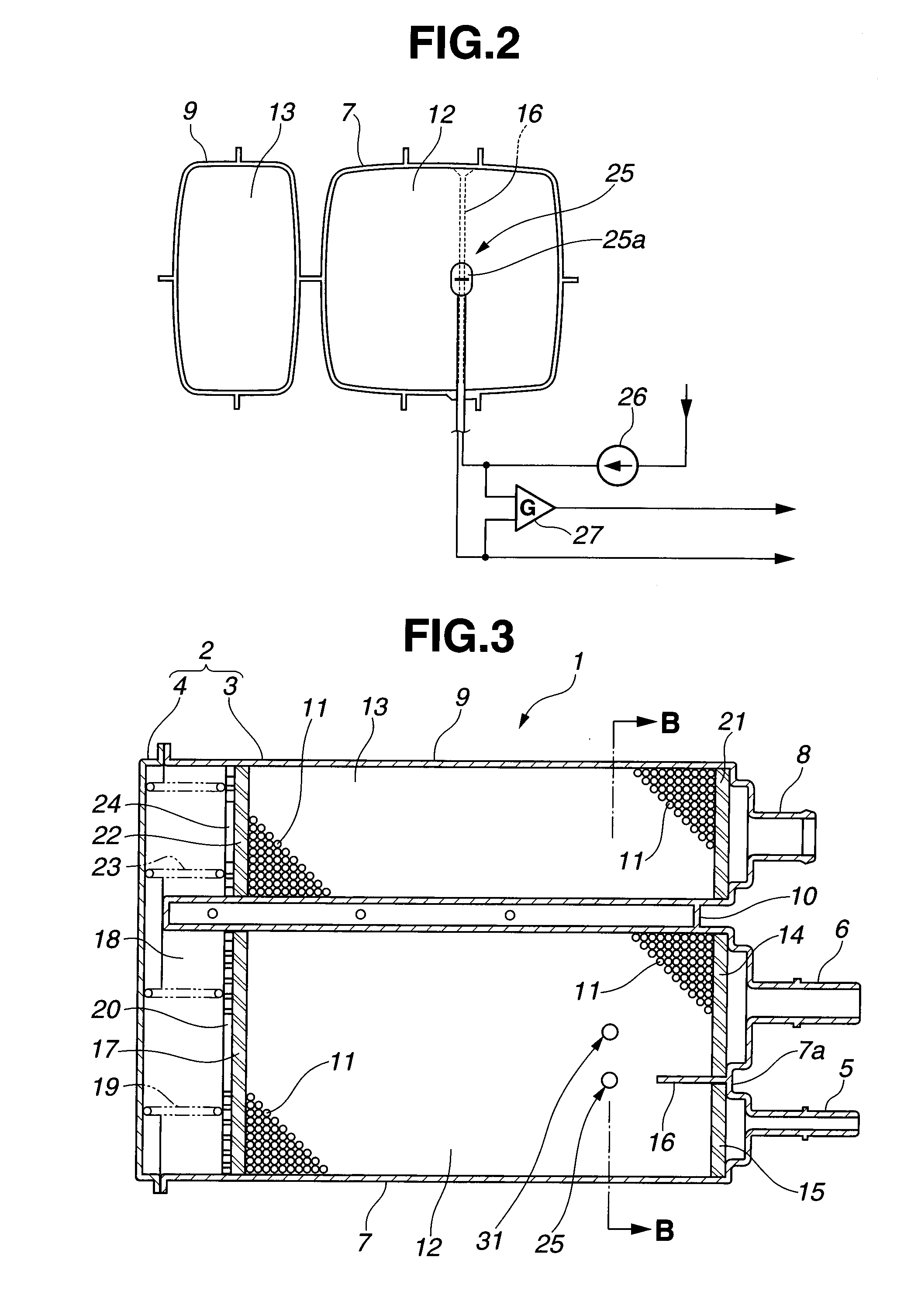
[0049]In the second embodiment, although the temperature sensor 31 is positioned apart from the hot-wire sensor 25 at the predetermined distance, this predetermined distance means that the temperature sensor 31 is disposed apart from the hot-wire sensor 25 at such distance that the temperature sensor 31 is unaffected by an influence of heat (heat generation) of the hot-wire sensor 25. The predetermined distance could be properly set in accordance with a magnitude of the constant current supplied to the hot-wire sensor 25 and / or material of the heating part 25a.

[0050]Next, a third embodiment will be explained with reference to FIG. 5. The structure of the third embodiment is basically same as the second embodiment. However, as can be seen in FIG. 5, a hot-wire sensor 41 as a second heat capacity detection means or device is provided and positioned at the other side of the first filling chamber 12. In other words, the hot-wire sensor 41 is located at the other end side of the flow pa...

third embodiment

[0052]In the third embodiment, the detection value of the hot-wire sensor 25 is detected by the same detection circuit as FIG. 4, and the detection value of the hot-wire sensor 41 is detected by the same detection circuit as FIG. 2. In addition, regarding the method of detecting the purge gas concentration from the detection value of the hot-wire sensor 41, it is the same as the above-mentioned method of estimating the purge gas concentration through the hot-wire sensor 25.

[0053]Furthermore, as described in each embodiment, when it becomes possible to accurately estimate the purge gas concentration upon execution of the purge before the engine start, the purge of the canister 1 can be executed without performing a so-called pre-purge (see FIG. 6. a related art requires the pre-purge for measurement of an exhaust air-fuel ratio and estimation of the purge gas concentration to determine a fuel injection quantity, whereas the present invention requires no pre-purge.). Therefore a purge...


PUM


Abstract

A purge gas concentration estimation apparatus has a canister having a casing that is filled with adsorbent which adsorbs and desorbs evaporated fuel and a heat capacity detection device that is disposed in the casing. The heat capacity detection device detects a heat capacity of an inside of the casing. An adsorption amount of the evaporated fuel that is adsorbed in the casing is detected from the heat capacity of the inside of the casing detected by the heat capacity detection device, and a purge gas concentration is estimated from the detected adsorption amount of the evaporated fuel.

Description

BACKGROUND OF THE INVENTION[0001]The present invention relates to a purge gas concentration estimation apparatus.[0002]In a vehicle using gasoline as fuel, a canister (a carbon or charcoal canister) is normally used as an evaporative fuel treatment apparatus, in order to prevent evaporated fuel in a fuel tank from discharging into the atmosphere. The canister performs the function of adsorbing and desorbing the evaporated fuel as follows: the evaporated fuel generated from the fuel tank in an engine halt state is adsorbed by an adsorbent which is made of the activated carbon. After that, by negative pressure generated by an intake of the engine, through the canister at engine start-up, an inside of the canister is purged with atmospheric air introduced from an air port. That is, the adsorbed evaporated fuel is desorbed from the adsorbent, and is burnt in the engine. The adsorbent therefore regains its adsorbing capability by the purge, and thus being able to adsorb the evaporated fu...

Claims


Application Information

Patent Timeline
Patent Type & Authority Patents(United States)
IPC IPC(8): G01M15/04
CPCF02M25/0827F02M25/0854
Inventor NAKANO, MASARU
Owner MAHLE FILTER SYST JAPAN CORP
Why Eureka
Try Eureka