Watertight junction box

a junction box and watertight technology, applied in the field of junction boxes, can solve the problems of shortening the work life and unable to prevent the permeation of water, and achieve the effect of long service life and conductive stability, without lowering the watertight sealing function

Active Publication Date: 2012-01-24
SMART ELECTRIC WORKS CO LTD
View PDF7 Cites 13 Cited by
  • Summary
  • Abstract
  • Description
  • Claims
  • Application Information

AI Technical Summary

Benefits of technology

[0005]The present invention has been accomplished under the circumstances in view. It is one object of the present invention to provide a watertight junction box, which utilizes a piece of silicon rubber to wrap about the connection area between the copper contacts and the installed power wire, protecting the copper contacts against oxidation and assuring a long service life and conductive stability.
[0006]It is another object of the present invention to provide a watertight junction box, which utilizes a piece of silicon rubber to assure watertight sealing and allows repeated use of the junction box without lowering its watertight sealing function.

Problems solved by technology

However, this design cannot prevent the permeation of water.
When used outdoor, rainwater may leak in, resulting in oxidation of the conductive metal clip sharp needle and shortening the work life.

Method used


Image

  • Watertight junction box
  • Watertight junction box
  • Watertight junction box

Examples


Embodiment Construction

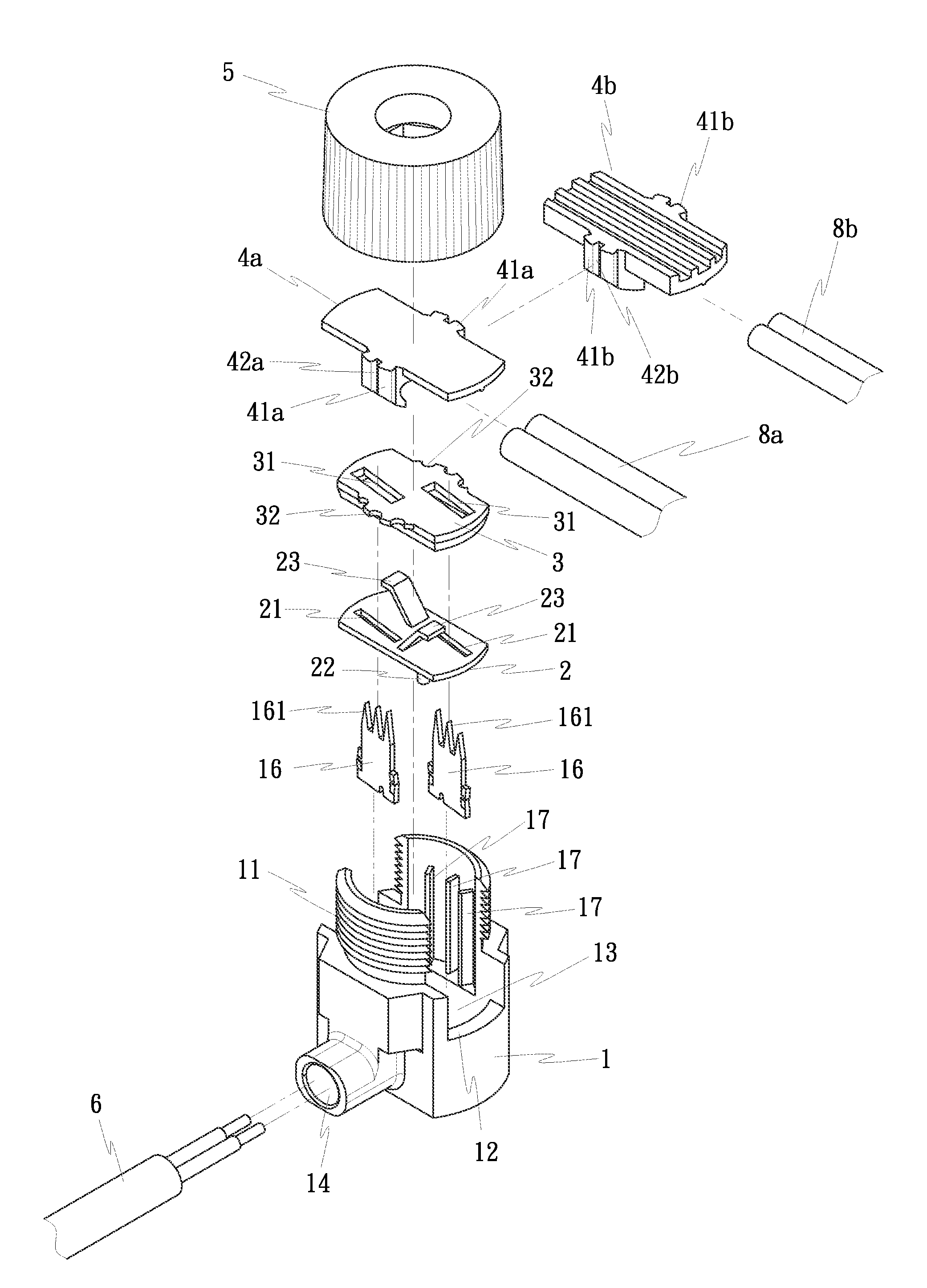
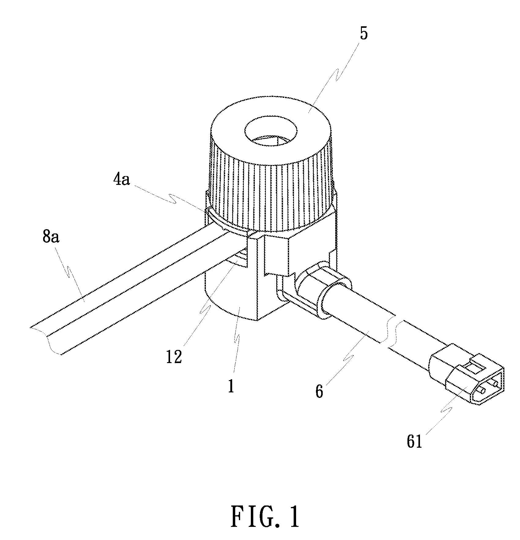
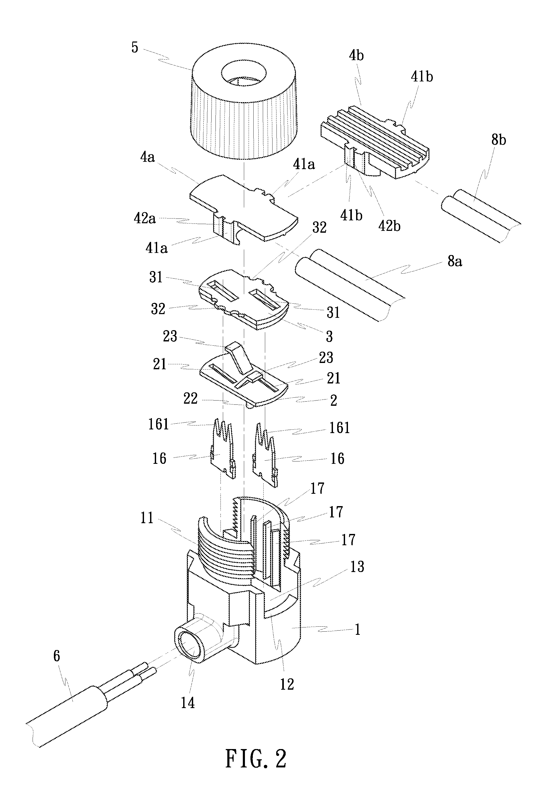
[0017]As shown in FIGS. 1˜5, a watertight junction box in accordance with the present invention comprises a box body 1, a lower floating plate 2, an upper floating plate 3, a holding down plate 4a or 4b and a lock cap 5.

[0018]The box body 1 is a hollow member comprising a threaded neck 11, an opening 12 transversely cut through the threaded neck 11 to separate the threaded neck 11 into two symmetrical halves, an accommodation chamber 13 defined beneath the threaded neck 11 (see FIG. 2 and FIG. 3), an insertion hole 14 cut through one side of the accommodation chamber 13 for the insertion of a modular cable 6 into the accommodation chamber 13, a partition board 15 disposed inside the accommodation chamber 13 (see FIG. 3 and FIG. 4), two copper contacts 16 mounted in the accommodation chamber 13 at two sides relative to the partition board 15 and a plurality of ribs 17 located on the inside wall of each of the two symmetrical halves of the threaded neck 11. Further, each copper contac...


PUM

PropertyMeasurementUnit
areaaaaaaaaaaa
thicknessaaaaaaaaaa
shapeaaaaaaaaaa

Abstract

A watertight junction box includes a box body, a lower floating plate, an upper floating plate, a lock cap, a modular cable inserted into the box body and kept in contact with sharp copper contacts, a holding down plate for holding down an external power wire on the upper floating plate to cause electric contact between the external power wire and the sharp copper contacts, and a predetermined amount of silicon rubber filled in between the lower and upper floating plate that is deformed to wrap about the connection area between the sharp copper contacts and the external power wire when the lock cap is tightly fastened to the box body to force down the holding down plate.

Description

BACKGROUND OF THE INVENTION[0001](a) Field of the Invention[0002]The present invention relates to junction boxes and more particularly to a watertight junction box, which facilitates rapid installation of wires and effectively prevents the permeation of water.[0003](b) Description of the Prior Art[0004]When connecting two electric wires together, the most commonly used method is to cut off the outer insulation of the connection end of each of the two electric wires, then to twist the bare metal conductors of the two electric wires together, and then to wrap the connection between the two electric wires with an insulative tape. Further, a junction box may be used for the connection of two electric wires. U.S. Pat. No. 5,499,931 discloses a lamp conducting structure in which power wires are pressed by the lower frame top central cylinder to cause the conductive metal clip sharp needle to cut off the outer insulations of the power wires to contact with the metal part of the power wires...

Claims


Application Information

Patent Timeline
Patent Type & Authority Patents(United States)
IPC IPC(8): H01R13/502
CPCH02G3/088H01R4/2408Y10T29/49007Y10S439/921
Inventor YANG, JERRY S. C.
Owner SMART ELECTRIC WORKS CO LTD
Why Eureka
Try Eureka