Electric power steering apparatus and method of assembling the same

a technology of electric power steering and motor, which is applied in the direction of gearing, dynamo-electric converter control, instruments, etc., can solve the problems of increasing electric loss, prolonging the durable life of board side connection terminals and motor side connection terminals, and increasing the structure of patent document 1 which cannot cope with phasing, so as to reduce manufacturing costs and reduce manufacturing costs. , the effect of high accuracy of positions

Active Publication Date: 2012-01-24
NSK LTD
View PDF21 Cites 658 Cited by
  • Summary
  • Abstract
  • Description
  • Claims
  • Application Information

AI Technical Summary

Benefits of technology

[0064]In this invention according to claim 25, since the fitting length of the output shaft of the electric motor and the worm shaft of the worm gear mechanism is set smaller than the inro fitting length of the motor body of the electric motor and the gear housing, even when the mass of the electric motor is large (axial direction length of the motor body is large), attachment length of the electric motor projecting from the gear housing is not so large. Therefore, in addition to the effect of the invention according to claim 24, it is possible to attach an electric motor having large mass to the gear housing.
[0065]Furthermore, an electric power steering apparatus according to claim 26 is an electric power steering apparatus including a steering column having inserted therein a steering shaft to which steering torque is transmitted, a reduction gear box coupled to the steering column, and an electric motor that transmits a steering assisting force to the steering shaft via a reduction mechanism in the reduction gear box. The electric power steering apparatus is characterized in that the electric motor and a control unit including a control board mounted with a control circuit that controls to drive the electric motor are provided side by side in the reduction gear box, a motor side connection terminal is formed in a position near the control unit of the electric motor, a control unit side connection terminal is formed in a position near the electric motor of the control unit, and at least one of the motor side connection terminal and the control unit side connection terminal is formed in at least one of the electric motor and the control unit with a predetermined dimensional tolerance, whereby the motor side connection terminal and the control unit side connection terminal are opposed to each other with a gap provided between the terminals, one of the control unit side connection terminal and the motor side connection terminal is formed in a flexible structure in which the connection terminal is elastically deformed in a direction toward the other of the control unit side connection terminal and the motor side connection terminal to absorb the gap and come into contact with the other connection terminal, and the other of the control unit side connection terminal and the motor side connection terminal is formed in a rigid structure in which the connection terminal cannot be deformed toward one of the control unit side connection terminal and the motor side connection terminal.
[0066]In this invention according to claim 26, since at least one of the motor side connection terminal and the board side connection terminal is formed in the flexible structure, the other is formed in the rigid structure, and one of the connection terminals is elastically deformed to electrically connect both the connection terminals, it is unnecessary to arrange the motor side connection terminal and the board side connection terminal in highly accurate positions and it is also unnecessary to form both the motor side connection terminal and the board side connection terminal in the flexible structure. Therefore, it is possible to realize a reduction in manufacturing cost.
[0067]An electric power steering apparatus according to claim 27 is characterized in that, in the invention according to claim 26, a long hole is formed at a distal end portion of one of the control unit side connection terminal and the motor side connection terminal formed in the flexible structure, a screw hole is formed in the other of the control unit side connection terminal and the motor side connection terminal formed in the rigid structure, the screw hole and the long hole of one and the other of the control unit side connection terminal and the motor side connection terminal are associated with each other, and a fixing screw is screwed into the screw hole through the long hole to electrically connect both the control unit side connection terminal and the motor side connection terminal.
[0068]In this invention according to claim 27, the long hole through which the fixing screw passes is formed in one of the board side connection terminal and the motor side connection terminal electrically connected by the fixing screw. Since the long hole is formed, it is possible to absorb fluctuation during manufacturing of the board side connection terminal and the motor side connection terminal. Therefore, it is possible to realize a further reduction in manufacturing cost.
[0069]Moreover, an electric power steering apparatus according to claim 28 is characterized in that, in the invention according to claim 26 or 27, one of the control unit side connection terminal and the motor side connection terminal formed in the flexible structure is a member formed in an L shape in a side view including a first elastic section extending toward the other of the control unit side connection terminal and the motor side connection terminal and a second elastic section extending from a distal end of the first elastic section in a direction along a connection surface of the other of the control unit side connection terminal and the motor side connection terminal.

Problems solved by technology

However, there are unsolved problems in that it is necessary to input a torque detection value of a torque sensor that detects torque transmitted to a steering shaft to the control board that controls the motor, since the torque sensor is usually set on a steering wheel side apart from the rack case or the steering gear box, it is necessary to provide a long connection cable between the torque sensor and the control board, electric noise mixes in the connection cable, and an electric loss increases because electric resistance increases.
Therefore, it is unnecessary to perform phasing for coupling the electric motor to the reduction mechanism.
In this case, there is an unsolved problem in that the structure of Patent Document 1 cannot cope with the phasing.
Therefore, there is a problem in terms of extension of durable life of the board side connection terminal and the motor side connection terminal.
On the other hand, when positions of the male terminal and the female terminal are highly accurately set to prevent the residual stress from occurring during connection, there is a problem in terms of manufacturing cost.
Therefore, generated heat in the control device cannot be efficiently transmitted to a gear box of a reduction gear having a large heat capacity and a large surface area via the electric motor.
However, there is an unsolved problem in that an increase in size of the control device is inevitable because the heat radiation fins are provided.

Method used


Image

  • Electric power steering apparatus and method of assembling the same
  • Electric power steering apparatus and method of assembling the same
  • Electric power steering apparatus and method of assembling the same

Examples


first embodiment

[0187]Next, operations in the first embodiment are explained.

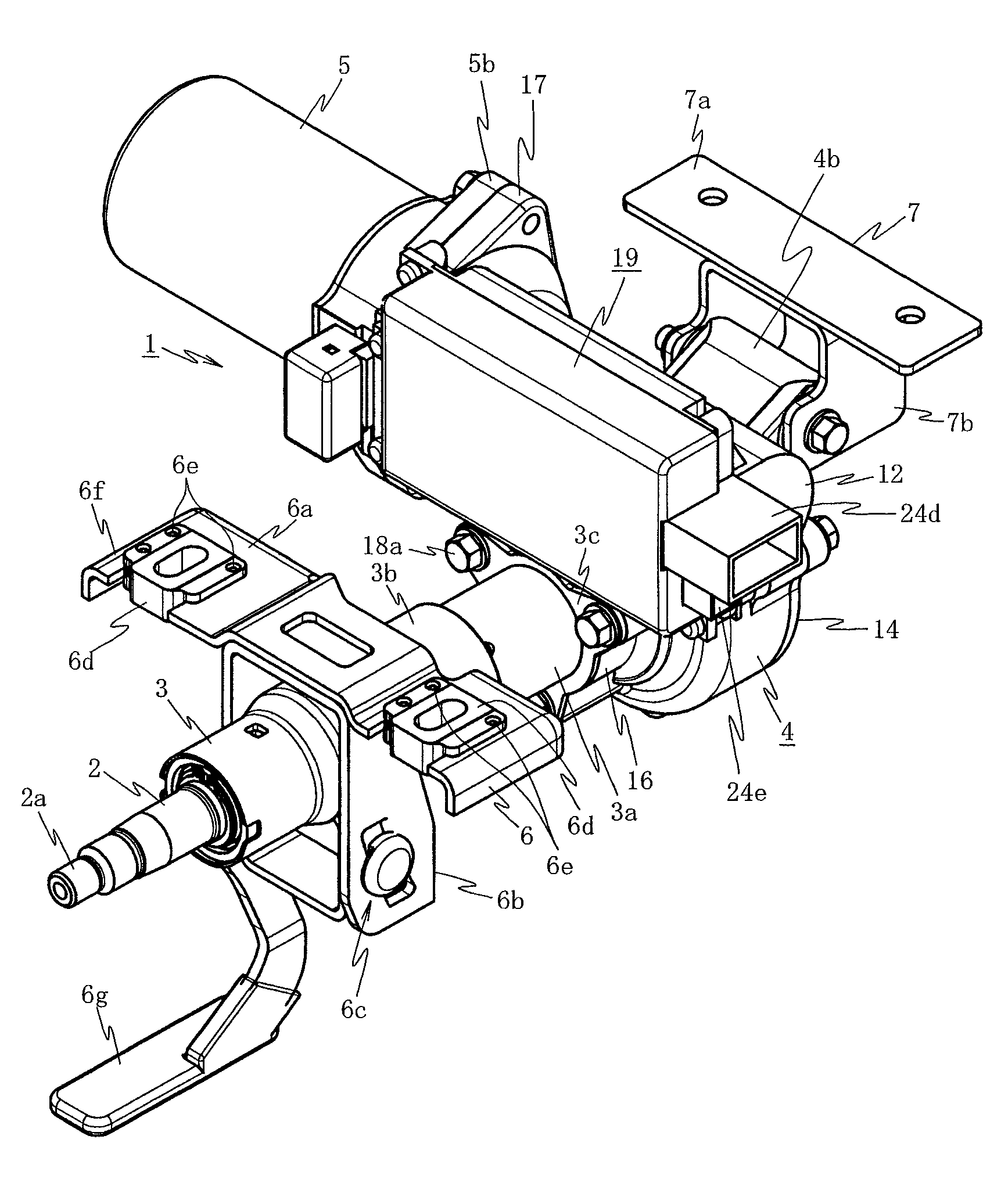
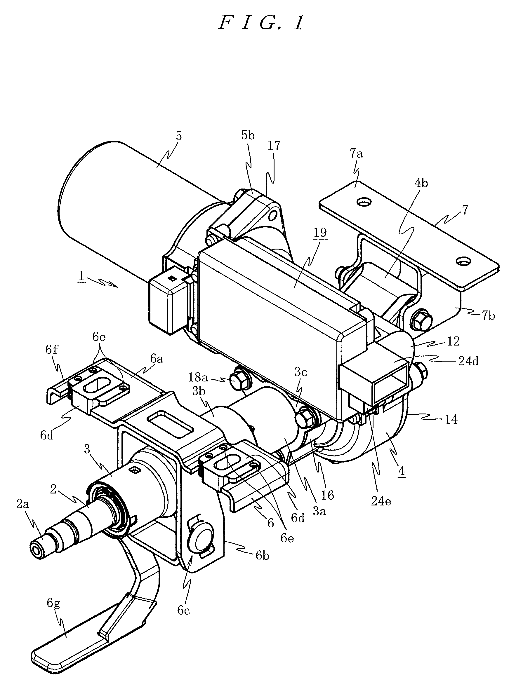
[0188]First, to assemble an electric power steering apparatus 1, the torque sensor 15 is fixedly arranged in the torque-sensor housing unit 16 of the reduction gear box 4 such that distal ends of the external connection terminals 15c to 15f thereof extend to the rear of the vehicle body along the outer peripheral portion of the steering column 3.

[0189]Subsequently, the control unit 19 is mounted on the control-unit mounting section 20 of the reduction gear box 4. In this mounting of the control unit 19, first, heat radiation grease is applied to the flat attaching surface 20a and, then, the power board 23 is placed on the heat radiation grease and screwed to the flat attaching surface 20a. In this state, the synthetic resin frame 24 is placed on the flat attaching surface 20a to surround the power board 23 and the attachment plate section 24b of the synthetic resin frame 24 is brought into contact with the frame attaching ...

second embodiment

[0213]Next, the present invention is explained with reference to FIGS. 22 and 23.

[0214]In this second embodiment, the contact surface of the motor-side connection section and the unit-side connection section is set in a direction parallel to the axial direction of the electric motor instead of the direction perpendicular to the axis of the electric motor.

[0215]In other words, in the second embodiment, as shown in FIG. 22, a height position on the steering wheel mounting section 2a side in an electric connection section 40 of the motor-side connection section of the electric motor 5 and the unit-side connection section of the control unit 19 is set to be equal to or lower than a height position on the steering wheel mounting section 2a of the control unit 19, i.e., not to further project than an end face on the steering wheel mounting section 2a of the control unit 19.

[0216]Therefore, as shown in FIGS. 23A to 23C, the connection terminals 5c and 5d as the motor-side connection sectio...

third embodiment

[0229]Next, the present invention is explained with reference to FIGS. 24 and 25.

[0230]In the third embodiment, the connection terminals 5c and 5d according to the second embodiment described above has flexibility.

[0231]In short, in the third embodiment, as shown in FIGS. 24 and 25, the motor-side connection section of the electric motor 5 includes a cable guide section 61 that has insulating properties and is opened at an upper end, has an insulating wall 61a in the center in the circumferential direction, and is fixed to an outer peripheral portion near an attachment end face 60 attached to the motor mounting section 17 of the reduction gear box 4 of the electric motor 5, two radial-direction plate sections 61b installed in two areas, which are defined by the insulating partition wall 61a of this cable guide section 61, and connected to the bus bars 5i and 5j, flexible cables 62 that are fastened by a fastening tool 61c to a projecting section projecting from the cable guide secti...


PUM


Abstract

A motor control apparatus includes a steering column having inserted therein a steering shaft to which steering torque is transmitted, a reduction gear box coupled to the steering shaft, and an electric motor that transmits a steering assisting force to the steering shaft via a reduction mechanism in the reduction gear box. The electric motor and its control unit including a control board mounted with a control circuit, are provided side by side in the reduction gear box. A connection terminal of the electric motor is electrically connected to the control unit directly. This minimizes a connection distance between the control unit and the electric motor.

Description

TECHNICAL FIELD[0001]The present invention relates to an electric power steering apparatus including a steering column having inserted therein a steering shaft to which steering torque is transmitted and an electric motor that transmits a steering assisting force to the steering shaft via a reduction mechanism in a reduction gear box, and to a method of assembling the same.BACKGROUND ART[0002]As an electric power steering apparatus in the past, for example, there has been proposed an electric power steering apparatus in which a motor is housed in a part of a rack case or a steering gear box in which a rack shaft is slidably housed or mounted, a housing in which a control board for controlling to drive the motor is housed is formed in the rack case or the steering gear box, and, when the control board inserted from an opening of the housing is brought into contact with an attachment boss formed in a bottom portion opposed to the opening, a board connection terminal provided in the co...

Claims


Application Information

Patent Timeline
Patent Type & Authority Patents(United States)
IPC IPC(8): G05D15/00
CPCB62D5/0406B62D5/0409F16H1/16H02K5/225H02K7/1166H02K11/0073H02K2211/03H02K11/33B62D5/04B62D1/19
Inventor SEKINE, TAKAAKIOOSHIMA, ATSUSHIKODAMA, TETSUYAKOBAYASHI, SEIICHISHIMIZU, YASUHIROHYOUDOU, NAOKIENDO, SHIGERUHORIKOSHI, ATSUSHIKASHIMOTO, KEIJIOUMI, TAMOTSUKAWADA, HIDEAKISHINOHARA, SHIGEOSENBA, TAKESHISHIMODA, MITSUO
Owner NSK LTD
Why Eureka
Try Eureka