
Method and spray tower for contacting gases and liquid droplets for mass and/or heat transfer

Active Publication Date: 2012-02-07
ANDRITZ ENERGY & ENVIRONMENT
View PDF21 Cites 4 Cited by
  • Summary
  • Abstract
  • Description
  • Claims
  • Application Information

AI Technical Summary

Benefits of technology

[0020]It is therefore an object of the invention to reduce the differences in the contact duration, and to direct the incoming flue gas predominantly into the internal region of the scrubber with a higher proportion of scrubbing liquid.
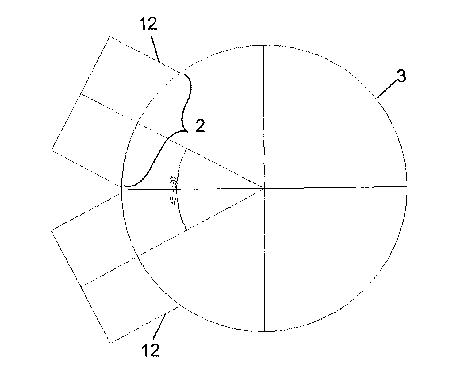
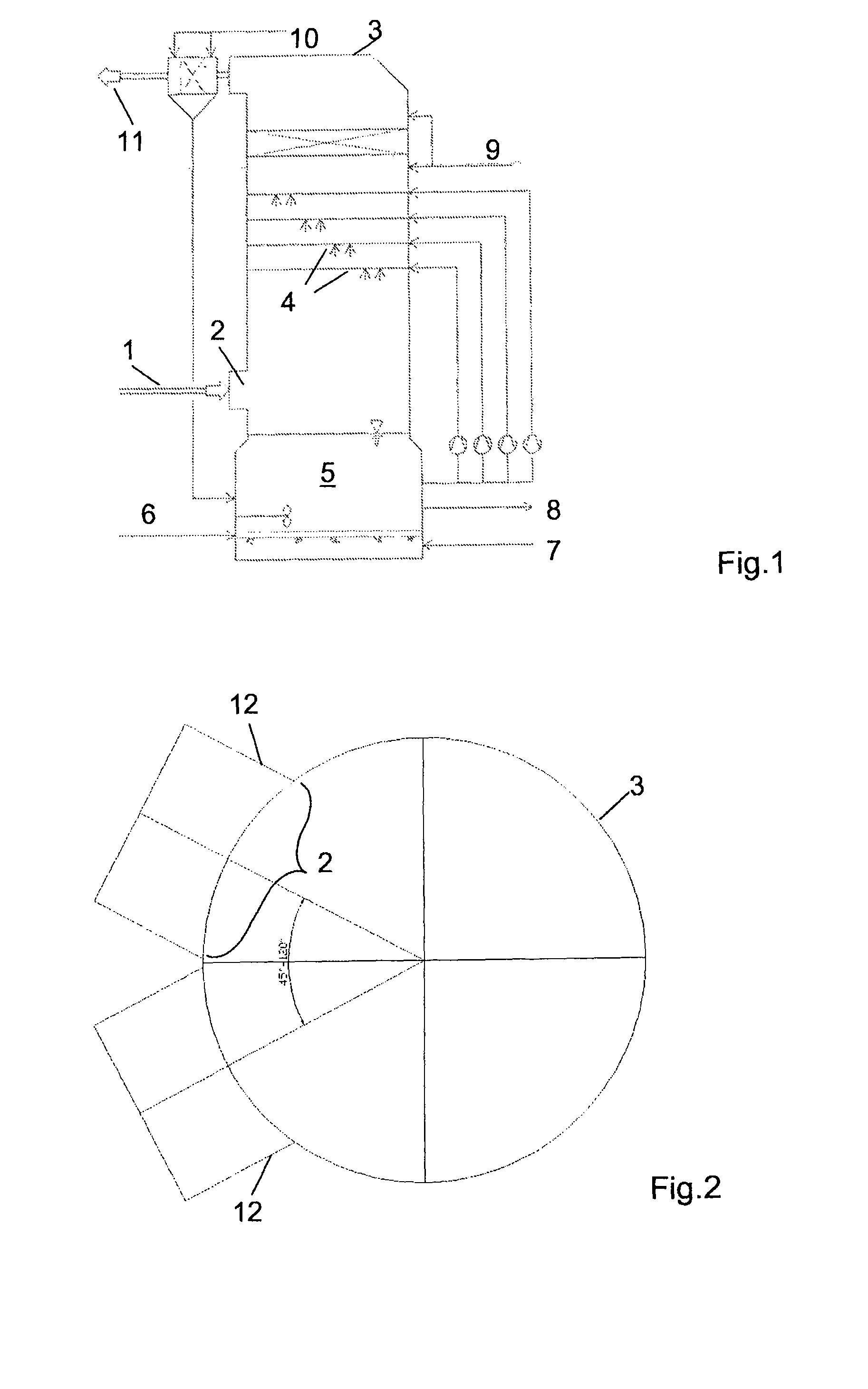
[0021]The gas is introduced through at least two inlet openings in the shell of the spray tower such that the flow directions of the at least two gas streams intersect on their extension inside the spray tower, the section in which the gas runs at the curved scrubber wall is minimized, and thus the lengthy horizontal movement of the gas at the spray tower wall is reduced. The edge flow is thereby reduced.
[0022]In addition, the gas flow is directed more strongly into the internal region of the spray tower to those zones with a higher liquid proportion. A more intensive interaction takes place between flue gas that is still unpurified or unconditioned and the liquid in the internal region of the contact zone, where a higher volume phase fraction of the liquid is also present.

Problems solved by technology

They can damage downstream heat-sensitive apparatuses, or impair their functioning.
It is even possible in relatively small apparatuses for stagnation point flows to form at the spray tower wall, in which case undesired increased upward gas velocities can arise at the spray tower wall by virtue of the deflection.
The gas movement is undesirably slowed down in a region in which the gas has already covered a lengthy path through the contact zone.
Similar problems also arise with the spray tower of DE 100 58 548 C1, where the gas is introduced tangentially into the spray tower through two separate opposite gas ducts.

Method used


Image

  • Method and spray tower for contacting gases and liquid droplets for mass and/or heat transfer
  • Method and spray tower for contacting gases and liquid droplets for mass and/or heat transfer
  • Method and spray tower for contacting gases and liquid droplets for mass and/or heat transfer

Examples


Embodiment Construction

[0042]A conventional open spray tower with a single radial introduction of gas for the purpose of flue gas desulfurization is illustrated in FIG. 1. The spray tower has a circular base surface and a cylindrical shell. The raw gas 1 is inlet horizontally into the contact region of the spray tower 3 through a single inlet opening 2. Suspension that gathers in the scrubber bottom 5 is injected in the spray tower from spray nozzles 4. Said scrubber bottom is gassed with the aid of oxidizing air 6. On the one hand, a portion of the suspension is led again from the bottom 5 into the spray nozzles 4 via circulating pumps, and on the other hand excess suspension is withdrawn via a line 8 to the hydrocyclone. Furthermore, fresh suspension 7 is fed to the bottom 5. Above the spray nozzles, the gas is purified using rinsing water 9, likewise after the outlet from the spray tower 3 by rinsing water 10 before it is withdrawn as pure gas 11.

[0043]The inventive spray tower in accordance with FIG. ...


PUM

PropertyMeasurementUnit
Lengthaaaaaaaaaa
Angleaaaaaaaaaa
Angleaaaaaaaaaa

Abstract

A method for contacting gases and liquid droplets for mass and / or heat transfer and a spray tower are disclosed, in which liquid is injected at a number of levels in counterflow to the gas, the gas being fed through at least two inlet openings in the shell of the spray tower. In this case, in order to reduce the differences in the contact duration, the flow direction of the gas at the inlet openings points into the internal region of the spray tower, which has a diameter of greater than or equal to 12 m, in particular greater than 20 m, such that the flow directions of the at least two gas streams intersect on their extension inside the spray tower, in particular at the center of the spray tower at up to half the spray tower radius downstream of the center of the spray tower.

Description

CROSS REFERENCE TO RELATED APPLICATION[0001]The present application is a 35 U.S.C. §§371 national phase conversion of PCT / EP2005 / 055451, filed Oct. 21, 2005 which claims priority of European Patent Application No. EP04026427, filed Nov. 8, 2004 and incorporated herein by reference. The PCT International Application was published in the German language.BACKGROUND OF THE INVENTION[0002]The invention relates to a method for contacting gases and liquid droplets for mass and / or heat transfer in a spray tower in which liquid is injected at a number of levels in counterflow to the gas, the gas being fed through at least two inlet openings in the shell of the spray tower, and to a corresponding spray tower.[0003]The invention can be applied in spray towers[0004]for mass transfer between gases and liquid (absorption, desorption), for example for absorbing pollutants from exhaust gases, for example for flue gas desulfurization (open spray scrubbers) from acid exhaust gases of combustion proce...

Claims


Application Information

Patent Timeline
IPC IPC(8): B01F3/04B01D53/50
CPCB01D53/18B01D53/78B01J10/002B01D53/77B01D53/50B01D47/00
Inventor MAIER, HERMANNWURZINGER, RAINER
Owner ANDRITZ ENERGY & ENVIRONMENT
Learn More