Turbine blade with micro channel cooling system

a cooling system and turbine blade technology, applied in the field of turbine blades with micro channel cooling systems, can solve the problems of insufficient cooling to split the total cooling flow, design problems, and failures, and achieve the effects of reducing cooling flow, reducing cross-over holes, and increasing the effectiveness of multi-pass serpentine cooling circuits

a cooling system and turbine blade technology, applied in the field of turbine blades with micro channel cooling systems, can solve the problems of insufficient cooling to split the total cooling flow, design problems, and failures, and achieve the effects of reducing cooling flow, reducing cross-over holes, and increasing the effectiveness of multi-pass serpentine cooling circuits

US8109726B2Inactive Publication Date: 2012-02-07SIEMENS ENERGY INC

Image

  • Turbine blade with micro channel cooling system
  • Turbine blade with micro channel cooling system
  • Turbine blade with micro channel cooling system

Examples


Embodiment Construction

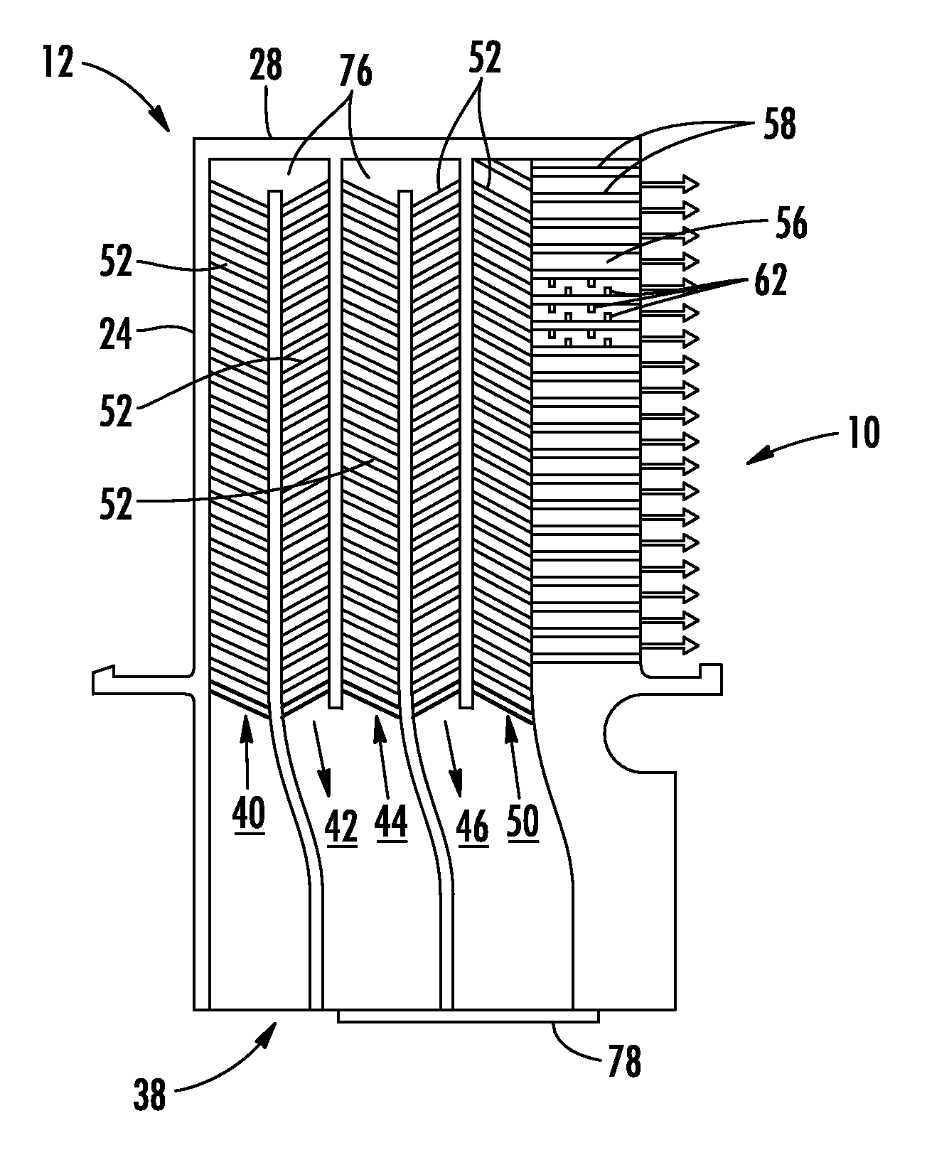
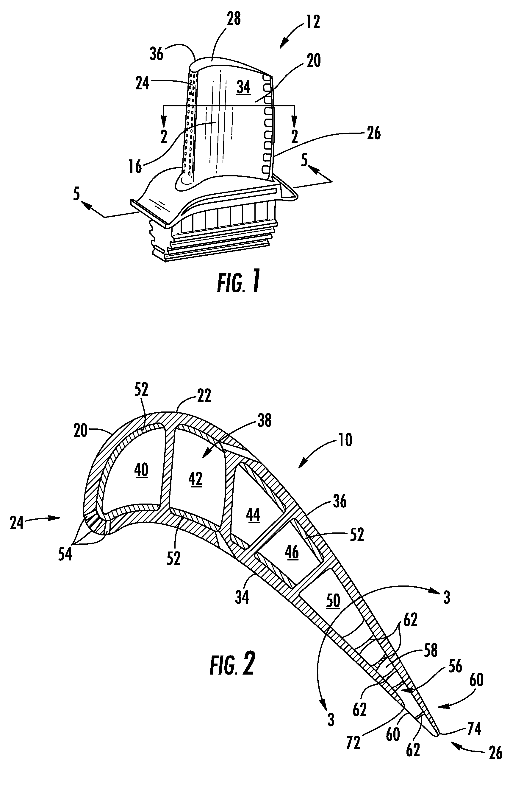
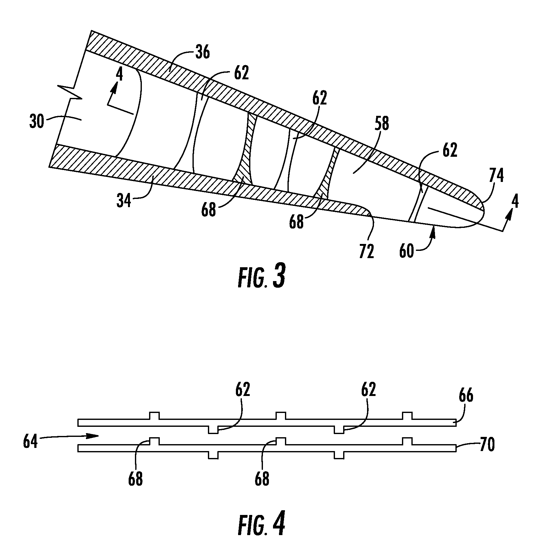
[0024]As shown in FIGS. 1-5, aspects of the invention is directed to a turbine airfoil cooling system 10 for a turbine airfoil 12 used in turbine engines. The airfoil 12 can include a generally elongated, hollow airfoil body 20 formed by an outer wall 22 extending chord wise from a forward leading edge 24 to a rearward trailing edge 26, a tip section 28 at a first span wise end, a root 30 coupled to the airfoil 20 at an end generally opposite the first tip end 28 span wise for supporting the airfoil 20 and for coupling the airfoil 20 to a disc (not shown), and a cooling system 10 formed from at least one cavity 32 in the elongated, hollow airfoil 20 positioned in internal aspects of the generally elongated, hollow airfoil 20. The outer wall 22 can include a concave pressure side wall 34 and a convex suction side wall 36 separated rearwardly by the trailing edge 26. The cooling system 10 has particular application to blades having a low cooling flow rate, such as blades coated with a...


PUM


Abstract

A cooling system for a turbine airfoil of a turbine engine has a multi-pass serpentine flow circuit providing a flow path from a forward cooling flow entry at the root and exhausting towards the trailing edge through a series of chord wise micro channels extending from the rearward pass of the multi-pass serpentine circuit to pressure side bleed slots, each having a forward pressure side lip and opening onto the pressure side adjacent the trailing edge. The micro channels can be formed by a series of spaced fins stacked span wise and extending between the outer wall on the pressure side and the outer wall on the suction side and extending chord wise from the rearward pass to the trailing edge. At least two trip strips can extend from sides of the fins into the micro channels and be staggered relative to trip strips extending into the micro channel from an adjacent fin, whereby turbulent flow levels in the micro channels are increased.

Description

FIELD OF THE INVENTION[0001]This invention is directed generally to turbine airfoils, and more particularly to cooling systems in hollow turbine airfoils.BACKGROUND[0002]Typically, gas turbine engines include a compressor for compressing air, a combustor for mixing the compressed air with fuel and igniting the mixture, and a turbine blade assembly for producing power. Combustors often operate at high temperatures that may exceed 2,500 degrees Fahrenheit. Typical turbine combustor configurations expose turbine blade assemblies to these high temperatures. As a result, turbine blades must be made of materials capable of withstanding such high temperatures. In addition, turbine blades often contain cooling systems for prolonging the life of the blades and reducing the likelihood of failure as a result of excessive temperatures.[0003]Typically, turbine blades are formed from a root portion having a platform at one end and an elongated portion forming a blade that extends outwardly from t...

Claims


Application Information

Patent Timeline
07 Feb 2012
Publication
US8109726B2
IPC
F01D5/08; F01D5/20
CPC
F01D5/187; F05D2240/122; F05D2240/304; F05D2250/185; F05D2230/90; F05D2260/22141
Inventors
LIANG, GEORGE