Managing reductant slip in an internal combustion engine

a reductant and internal combustion engine technology, applied in the direction of machines/engines, electric control, instruments, etc., can solve the problems of reductant slip, reductant slip, reductant slip, etc., to reduce or inhibit increase the amount of reductant released, and reduce the effect of reducing or inhibiting the amount of reductant injected

Active Publication Date: 2012-02-14
FORD GLOBAL TECH LLC
View PDF14 Cites 13 Cited by
  • Summary
  • Abstract
  • Description
  • Claims
  • Application Information

AI Technical Summary

Benefits of technology

[0003]A reductant slip may increase the amount of reductant released into the atmosphere. Furthermore, during or subsequent to a reductant slip, when an emission control device, such as a diesel particulate filter DPF, is located downstream of the SCR system, a reductant, such as ammonia, may be converted back to NOx due to the presence of platinum in the DPF. Therefore, reductant slip may increase emissions from the vehicle under some operating conditions.
[0004]Various approaches try to reduce or inhibit the amount of reductant injected into the exhaust stream to reduce reductant slip caused by desorption of reductant from SCR catalyst brick. For example, in U.S. Pat. No. 6,415,602, catalyst temperature is filtered using a variable time constant corresponding to current space velocity of the exhaust gas to account of the changes in the catalyst temperature attributed to NOx transient emissions. Therefore, the amount of reductant is metered on the basis of a filtered NOx concentration applied at a normalized stoichiometric ratio. In this way, the amount of reductant injected into the exhaust stream is adjusted based on the catalyst temperature. Specifically, as the storage ability of the catalyst decreases with temperature, the reductant is metered accordingly to reduce reductant slip.
[0005]However, reductant slip may occur regardless of the amount of reductant injected into the exhaust stream, and even when no reductant is injected. For example, the catalyst temperature may experience significant and rapid temperature changes based on various vehicle operating conditions, as well as the ambient conditions. Under the aforementioned conditions, the catalyst may experience reductant slip due to the correspondence between reductant storage capacity in the catalyst and catalyst temperature. For example, if the catalyst temperature changes, thereby changing the reducant storage capacity to below the current amount of stored reductant, the excess reductant can be released, even if no reductant is injected. Such changes can occur during either increasing or decreasing temperature, as changes in either direction can reduce storage capacity due to the non-linear relationship of storage capacity to temperature.
[0007]In this way, the exhaust reducant release from the catalyst may be reacted, decreasing emissions from the vehicle as well as decreasing inefficiencies in the system. In some examples, the amount of NOx produced in combustion may be increased until a sufficient amount of NOx is produced to react with the reductant released from the catalyst. Subsequent to the release of the reductant and the increase in NOx production, NOx production may be reduced to avoid increased emissions. However, if the storage capacity of the catalyst continues to drop, an increased amount of NOx will be produced. In this way, the NOx production corresponds to the amount of reductant released from the catalyst.

Problems solved by technology

However, the storage capacity, as well as the absorption and desorption rates of the reductant into the catalyst, may fluctuate with temperature and other variables.
However, during some operating conditions, such as transient operation, reductant slip may occur when the reductant storage capacity in the SCR catalyst drops below the amount of reductant stored.
Therefore, reductant slip may increase emissions from the vehicle under some operating conditions.
However, reductant slip may occur regardless of the amount of reductant injected into the exhaust stream, and even when no reductant is injected.
Under the aforementioned conditions, the catalyst may experience reductant slip due to the correspondence between reductant storage capacity in the catalyst and catalyst temperature.
Such changes can occur during either increasing or decreasing temperature, as changes in either direction can reduce storage capacity due to the non-linear relationship of storage capacity to temperature.

Method used


Image

  • Managing reductant slip in an internal combustion engine
  • Managing reductant slip in an internal combustion engine
  • Managing reductant slip in an internal combustion engine

Examples


Embodiment Construction

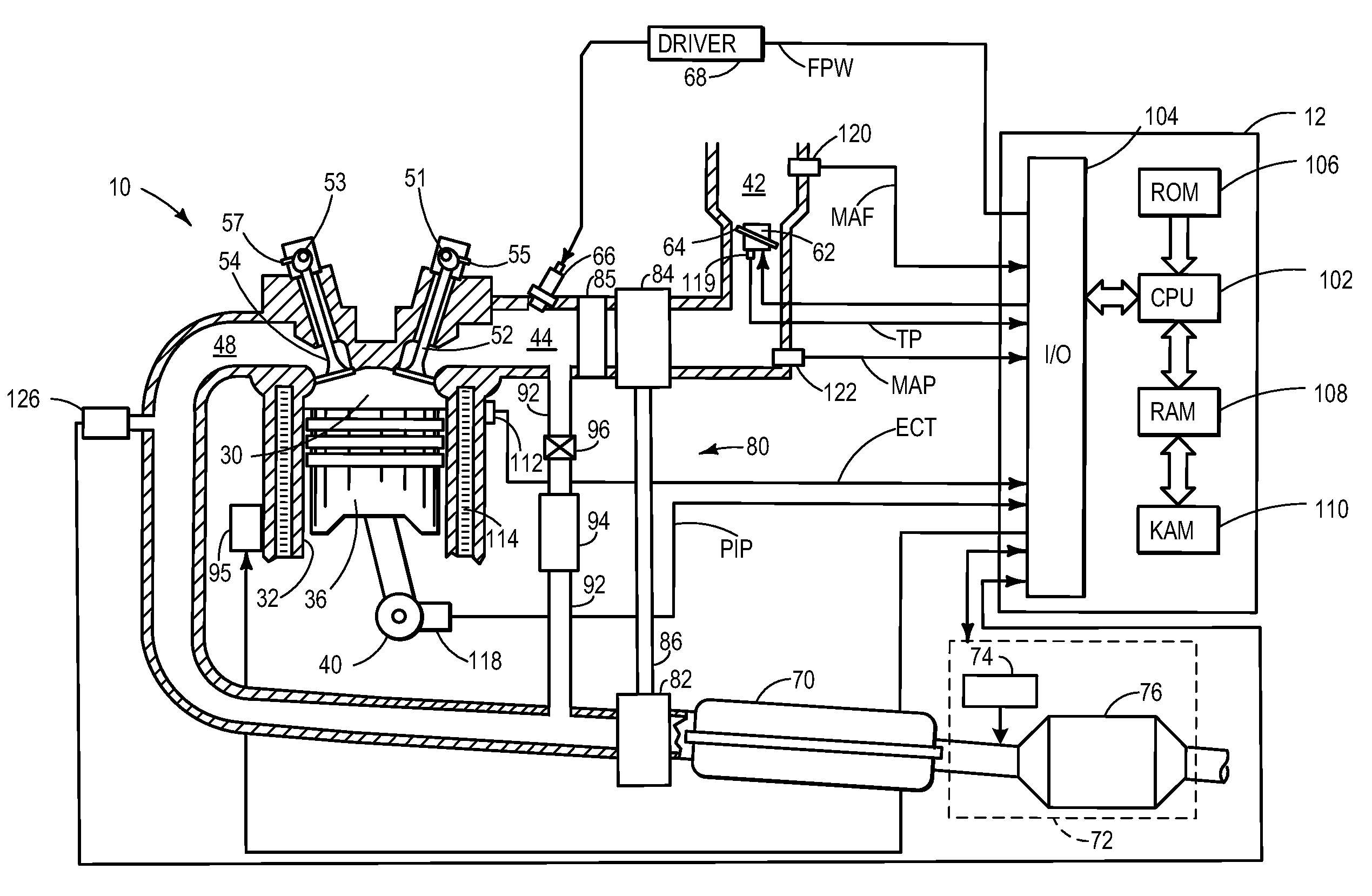
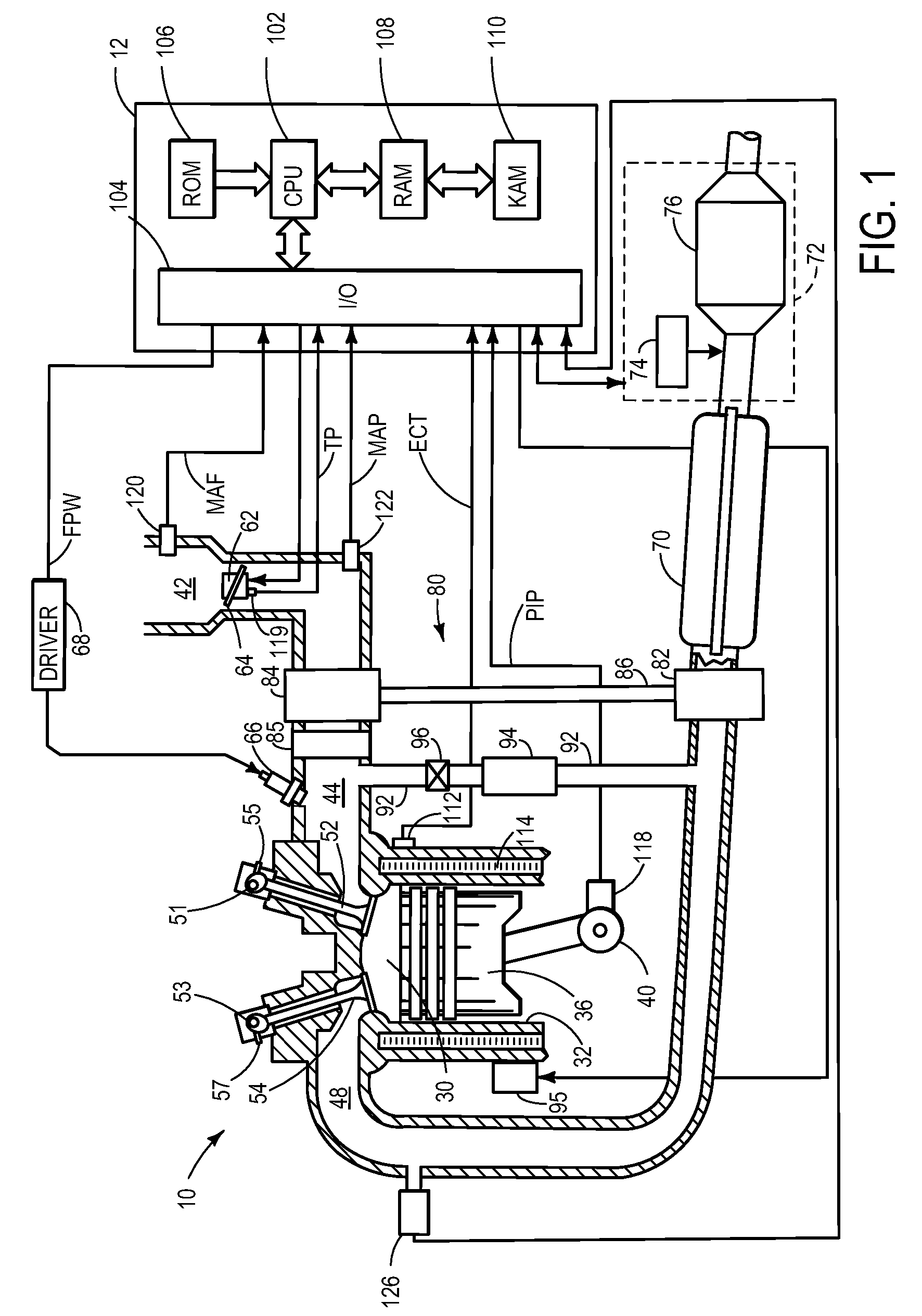
[0017]Referring now to FIG. 1, internal combustion engine 10, comprising a plurality of combustion chambers and controlled by electronic engine controller 12, is shown. Combustion chamber 30 (e.g. cylinder) of engine 10 includes combustion chamber walls 32 with piston 36 positioned therein and connected to crankshaft 40. In one example, piston 36 includes a recess or bowl (not shown) to form selected levels of stratification or homogenization of charges of air and fuel. Alternatively, a flat piston may also be used.

[0018]Combustion chamber 30 is shown communicating with intake manifold 44 and exhaust manifold 48 via intake valve 52, and exhaust valve 54. Fuel injector 66 is shown coupled upstream of the intake valve providing what is known as port injection. The fuel injector delivers liquid fuel directly therein in proportion to the pulse width of signal fpw received from controller 12 via conventional electronic driver 68. Additionally or alternatively the fuel injector may be dir...


PUM


Abstract

A method for controlling operation of vehicle system including an internal combustion engine and a catalytic emission control device coupled in an exhaust of the engine, the method including delivering, which may include injecting into the exhaust, reductant to the emission control device responsive to vehicle operating conditions, and increasing emission control device inlet-NOx in response to reductant release from the emission control device.

Description

BACKGROUND AND SUMMARY[0001]Selective catalytic reduction (SCR) systems have been used to reduce automotive emissions. Such systems typically add a gaseous or liquid reductant, such as ammonia or urea, to the engine exhaust gas stream. The reductant may be absorbed onto a catalyst where the reductant reacts with nitrogen oxides in the exhaust gas to form water vapor and nitrogen. However, the storage capacity, as well as the absorption and desorption rates of the reductant into the catalyst, may fluctuate with temperature and other variables.[0002]A release of unreacted reductant from an SCR catalyst may be referred to as reductant slip. Under some conditions, the amount of reductant stored in an SCR catalyst may be increased to boost the NOx conversion in the SCR system. However, during some operating conditions, such as transient operation, reductant slip may occur when the reductant storage capacity in the SCR catalyst drops below the amount of reductant stored.[0003]A reductant ...

Claims


Application Information

Patent Timeline
Patent Type & Authority Patents(United States)
IPC IPC(8): F01N3/00F01N3/10
CPCF01N3/208F02B37/16F02D41/1462F01N2610/02F01N2900/1602F02B29/0406F02B37/22F02D41/0055F02D41/0275F02M25/0707F02M25/0727Y02T10/144Y02T10/24F02M26/05F02M26/23Y02A50/20Y02T10/12
Inventor KURTZ, ERIC MATTHEW
Owner FORD GLOBAL TECH LLC
Why Eureka
Try Eureka