Blood pump and pump unit

a technology of pump unit and blood pump, which is applied in the direction of prosthesis, liquid fuel engine, therapy, etc., can solve the problems of blood clots and the inability to maintain the sealing durability, and achieve the effect of low manufacturing cost and high reliability

Active Publication Date: 2012-02-14
NIPRO CORP
View PDF19 Cites 86 Cited by
  • Summary
  • Abstract
  • Description
  • Claims
  • Application Information

AI Technical Summary

Benefits of technology

[0019]The present invention enables the impeller to be rotatably supported in the casing in a noncontact manner both in the axial direction and the radial direction with low manufacturing cost, and eliminates the need for controlling magnetic force, thereby ensuring high reliability.

Problems solved by technology

However, because the axial sealing structure is in contact with the casing and the rotating shaft, red blood cells and other components in the blood may be damaged at these points of contact to cause hemolysis, and stagnant blood flow at the points of contact may cause a blood clot.
In addition, an issue may arise with durability of the sealing.

Method used


Image

  • Blood pump and pump unit
  • Blood pump and pump unit
  • Blood pump and pump unit

Examples


Embodiment Construction

[0053]Embodiments of a blood pump and a pump unit according to the present invention will now be explained in detail with reference to the accompanying drawings. These embodiments are not intended to limit the present invention. Constituent elements in the embodiments below include elements readily substituted by those skilled in the art and substantially equivalent elements.

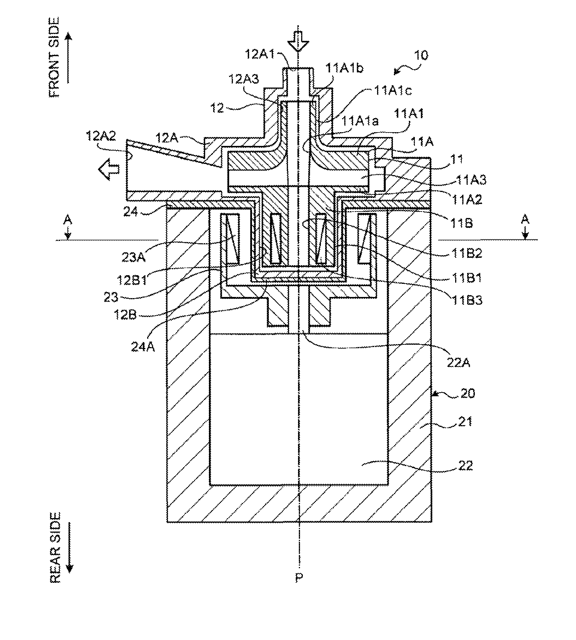
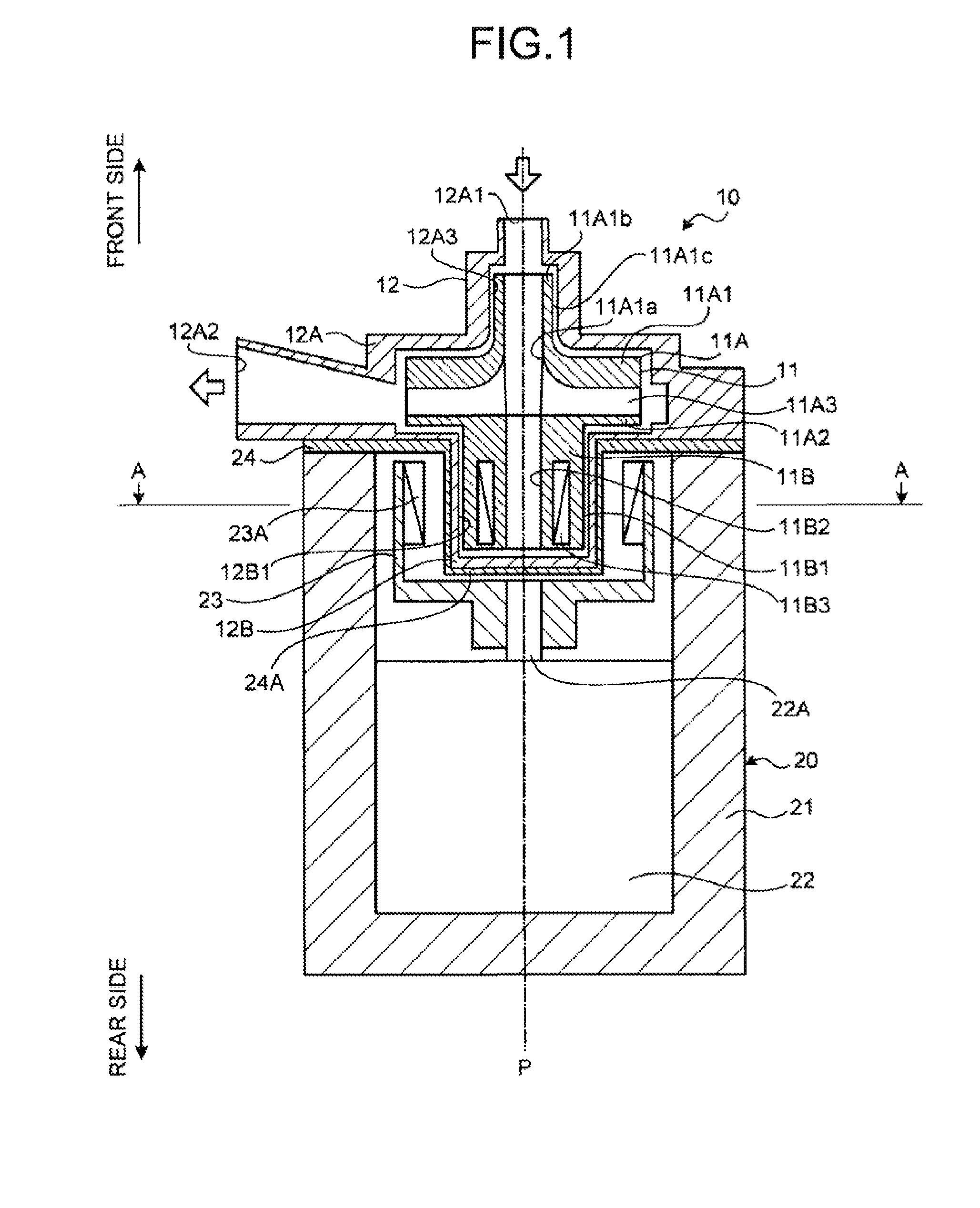
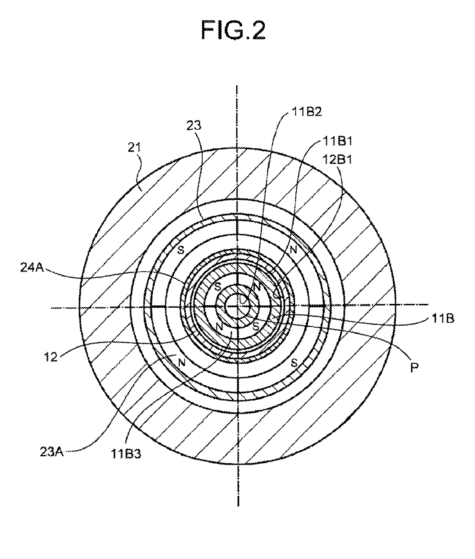
[0054]FIG. 1 is a schematic sectional view of a blood pump according to an embodiment of the present invention. FIG. 2 is a sectional view along A-A in FIG. 1. FIG. 3 is a schematic sectional view of the blood pump illustrated in FIG. 1 in a detached state. As illustrated in FIG. 1, the blood pump according to the embodiment of the present invention includes a pump unit 10 and a driving unit 20.

[0055]The pump unit 10 includes a rotating body 11 and a casing 12.

[0056]The rotating body 11 has an impeller 11A and a shaft 11B. The impeller 11A is configured as a closed impeller having a front shroud 11A1, a rear shr...


PUM


Abstract

Provided are a magnetic coupling as an axial bearing including a driven magnet (11B3) that is a permanent magnet provided to a rotating body (11) inside a casing (12) and a drive magnet (23A) that is a permanent magnet placed face to face with the driven magnet in a radial direction of the rotating body outside the casing to be magnetically coupled with the driven magnet, a driving motor (22) that rotatably drives the drive magnet about an axis (P) of the rotating body, a radial bearing that is a dynamic bearing having annular bearing surfaces (12B1, 11B1) centering on the axis on an inner wall of the casing and the rotating body, each of the annular bearing surfaces being arranged with a gap between the drive magnet and the driven magnet in the radial direction of the rotating body, and a closed impeller (11A) including a front shroud (11A1) arranged on a front side in the axis direction in the rotating body, a rear shroud (11A2) arranged on a rear side in the axis direction of the front shroud, and a vane (11A3) arranged between the front shroud and the rear shroud.

Description

TECHNICAL FIELD[0001]The present invention relates to a blood pump and a pump unit for pumping blood.BACKGROUND ART[0002]In open-heart surgery, a blood pump for pumping blood is used to maintain the blood circulation. A known blood pump includes a casing, an impeller rotatably arranged in the casing, and a driving mechanism causing the impeller to rotate, and causes the impeller to rotate by the driving mechanism to take blood into a channel inside the casing and pump the blood outside the casing.[0003]In this type of blood pump, for example, a rotating shaft for the impeller penetrates the wall of the casing and projects from the casing, and a driving motor is connected to the rotating shaft. In an area where the rotating shaft penetrates the wall of the casing, an axial sealing structure is provided to prevent leakage of blood. However, because the axial sealing structure is in contact with the casing and the rotating shaft, red blood cells and other components in the blood may be...

Claims


Application Information

Patent Timeline
Patent Type & Authority Patents(United States)
IPC IPC(8): A61M1/10A61M60/117A61M60/216A61M60/419A61M60/806
CPCA61M1/101F04D29/047F04D29/048F04D13/026A61M1/1017A61M1/1036A61M60/824A61M60/419A61M60/216A61M60/806A61M60/117
Inventor HIDAKA, TATSUYAOKUBO, TAKESHIYAMAMOTO, YASUHARUOSADA, TOSHIYUKITAGAWA, MASASHI
Owner NIPRO CORP
Why Eureka
Try Eureka