Separator to separate a liquid/liquid/gas/solid mixture

a technology of liquid/gas/solid mixture and separator, which is applied in the direction of liquid degasification, separation process, and other chemical processes, can solve problems such as production bottlenecks, and achieve the effects of high turn down ratio, reliable removal method, and high production economics and recoverable reserves

Active Publication Date: 2012-02-14
DPS BRISTOL HOLDINGS LTD
View PDF9 Cites 23 Cited by
  • Summary
  • Abstract
  • Description
  • Claims
  • Application Information

AI Technical Summary

Benefits of technology

[0024]It is an advantage of the invention that it provides a reliable method of removing, at least 80% of the produced water from a well bore stream. It also provides management of solids, so that the liquid volumetric flowrates to a riser or through an existing separation process are reduced, thus allowing more wells to be drilled and produced with existing facilities. This in many cases could increase the production economics and recoverable reserves of both existing oil production facilities offshore, new offshore installations and offshore marginal fields.
[0025]Advantageously, the system is able to manage slugs of fluids and solids without a process upset, hence affording the separator a high turn down ratio for each phase to be separated.

Problems solved by technology

The larger oil discoveries are now in the minority, and are in many instances starting to, or are, suffering a production bottleneck caused by high water production rates.

Method used


Image

  • Separator to separate a liquid/liquid/gas/solid mixture
  • Separator to separate a liquid/liquid/gas/solid mixture
  • Separator to separate a liquid/liquid/gas/solid mixture

Examples


first embodiment

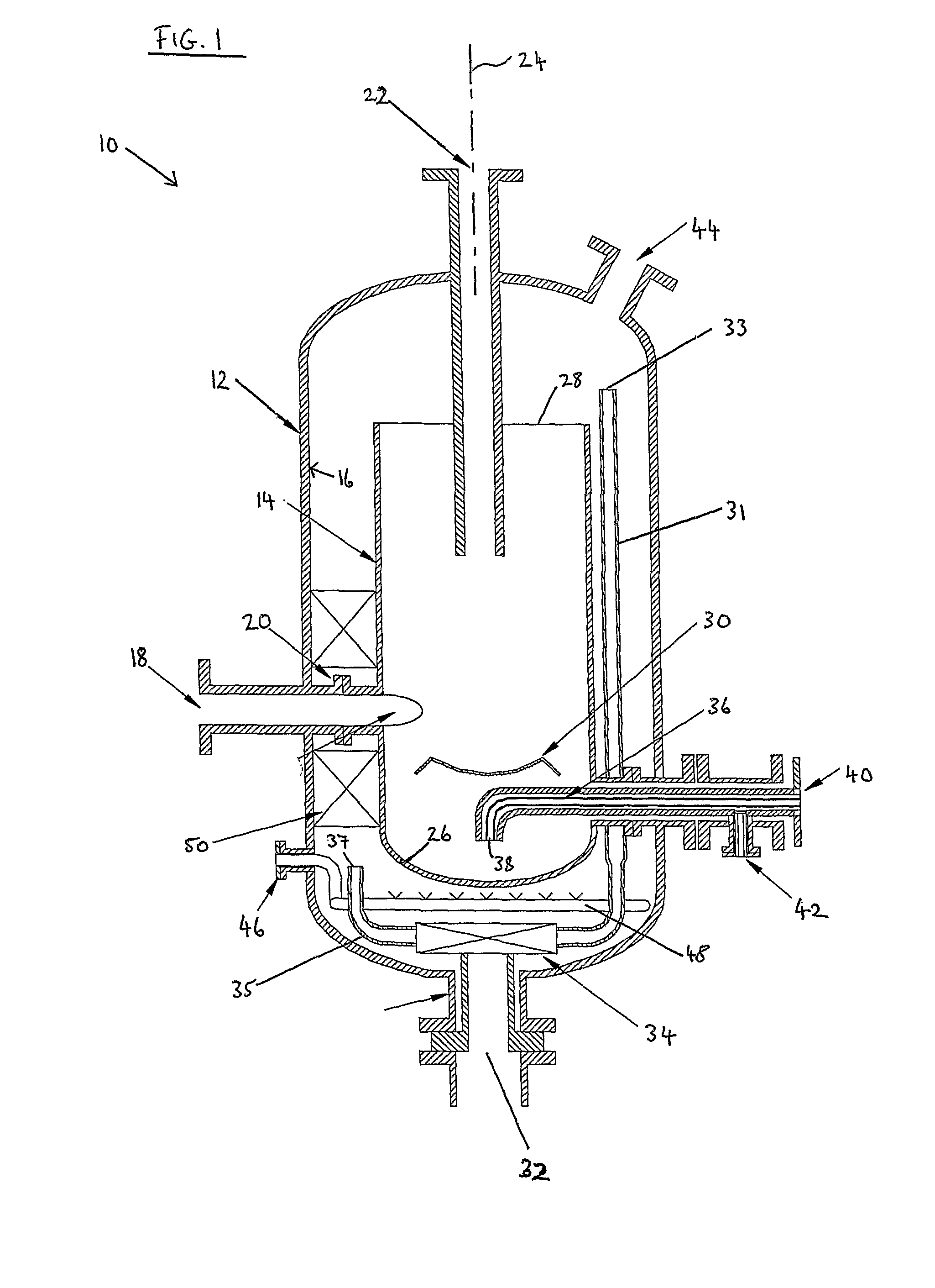
[0030]Referring firstly to FIG. 1, a separator is indicated generally at 10. The separator comprises a pressure vessel or tank 12 and a cyclone 14 mounted within the pressure vessel 12, spaced from the wall 16 of the pressure vessel. The pressure vessel 12 is substantially cylindrical with domed ends, and has a central vertical axis indicated at 24. The cyclone 14 is mounted coaxially inside the pressure vessel 12. An inlet passage 18 extends through the wall 16 of the pressure vessel 12, across an internal annular space 20 between the pressure vessel and the cyclone 14, and into the cyclone 14. The inlet passage 18 opens into the cyclone 14 tangentially, and is shaped to cause fluids entering the cyclone through the passage 18 to rotate, and hence to cause a swirling flow or vortex flow regime in the cyclone 14.

[0031]The cyclone 14 is also substantially cylindrical, with a closed lower end 26 and an open upper end 28. A core finder 30, alternatively known as a vortex seat, is posit...

second embodiment

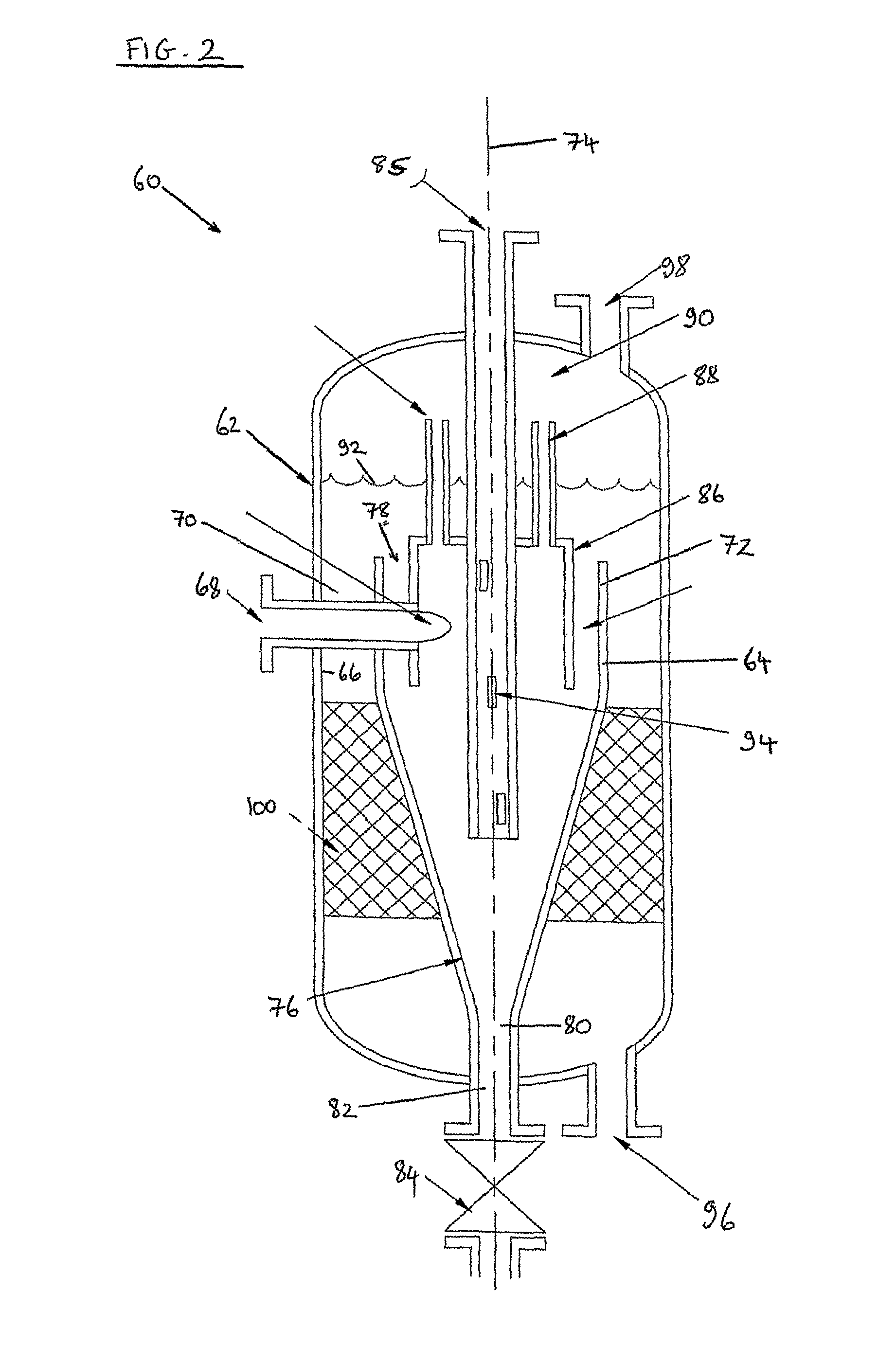
[0043]Referring now to FIG. 2, a separator is indicated at 60. The separator 60 comprises a pressure vessel or tank 62 and a cyclone 64 mounted within the pressure vessel 62, spaced from the wall 66 of the pressure vessel. The pressure vessel 62 is substantially cylindrical with domed ends, and has a central vertical axis indicated at 74. The cyclone 64 is mounted coaxially inside the pressure vessel 62. An inlet passage 68 extends through the wall 66 of the pressure vessel 62, across an internal annular space 70 between the pressure vessel and the cyclone 64, and into the cyclone. The inlet passage 88 opens into the cyclone 64 tangentially, and is shaped to cause fluids entering the cyclone through the passage 68 to rotate, and hence to cause a swirling flow or vortex flow regime in the cyclone 64.

[0044]The cyclone 64 has a substantially cylindrical upper portion 72, an open upper end 78, a conical lower portion 76 and a lower end 80 leading to an exit passage 82 and a valve 84, wh...


PUM

PropertyMeasurementUnit
retention) timeaaaaaaaaaa
pressureaaaaaaaaaa
volumesaaaaaaaaaa

Abstract

A separator for separating or partially separating oil, water, gas and solids from hydrocarbon production well fluids comprises a vessel and a cyclone contained within the vessel. An inlet passage passes through a wall of the vessel and into the cyclone, the inlet passage having means for causing the flow to rotate within the cyclone. A first outlet passage for an oil rich phase extends from a position within the cyclone and substantially on a central axis of the cyclone; a second outlet passage for a water phase extends from a base of the vessel; and a third outlet passage for the solids extends from a lower end of the cyclone.

Description

[0001]The present invention relates to a separator and particularly, but not exclusively, to a separator for separating or partially separating oil, water, gas and solids from hydrocarbon production well fluids.BACKGROUND TO INVENTION[0002]Production of hydrocarbons particularly from remote or marginal oil and gas fields offshore is proving to be of significant importance to oil companies, and the economies of some oil producing countries. The larger oil discoveries are now in the minority, and are in many instances starting to, or are, suffering a production bottleneck caused by high water production rates. It is the economic field life extension of these and the development of the smaller reserves of recoverable oil, particularly in deep water, or a long distance from any other facilities, that creates the need for a new generation compact separator.[0003]To continue to produce or bring into production such fields in an economically and environmentally secure method, it would be b...

Claims


Application Information

Patent Timeline
Patent Type & Authority Patents(United States)
IPC IPC(8): C02F1/24B01D19/00B01D21/24B04C5/12
CPCB01D17/0217B01D21/267B01D21/2411B01D21/2444B01D21/245B01D21/2472B04C5/12B04C5/18C10G33/06B01D19/0057B01D21/26B01D2221/04C10G2300/1033B01D21/34B04C3/04B04C3/06B04C5/04B04C7/00B01D21/24
Inventor PARKINSON, DAVID J.
Owner DPS BRISTOL HOLDINGS LTD
Why Eureka
Try Eureka