
Ultra-wideband antenna having a band notch characteristic

a technology of ultra-wideband antennas and characteristic bands, applied in the direction of resonant antennas, substantially flat resonant elements, elongated active element feeds, etc., can solve the problems of interference with the uwb system, difficulty in wiretapping, and difficulty in extending so as to improve the characteristic of antennas at intermediate frequency bands, the effect of expanding the bandwidth of antennas and light weigh

Inactive Publication Date: 2012-02-14
EMW CO LTD
View PDF40 Cites 3 Cited by
  • Summary
  • Abstract
  • Description
  • Claims
  • Application Information

AI Technical Summary

Benefits of technology

The design expands bandwidth, improves antenna characteristics at intermediate frequencies, and provides a band-stop characteristic at the UNII band, reducing interference and enabling high-speed, low-power communication with reduced size and weight, suitable for next-generation WPANs.

Problems solved by technology

Furthermore, since power is diffused over a wide band, each frequency component requires very low power.
This makes the UWB system less interfere with other communication systems that employ a narrow frequency band and also makes wiretapping difficult.
However, these antennas are problematic in that they are inappropriate for the fields requiring small and lightweight antennas because of its size.
These standards may cause interference with the UWB system in the UNII band since a high-power signal is used.
Accordingly, in the UWB system, the use of the UNII frequency band overlapped with that of the wireless LAN is limited.
However, the antennas disclosed in the above U.S. Patents and Korean Patent Applications have only the UWB characteristic, but do not have a band-stop characteristic at a frequency band whose use is limited.
However, to add the band-stop filter not only increases the cost, but also limit the miniaturization and light weight of an equipment.
The addition of the band-stop filter also causes the distortion of a pulse in the UWB system using a very short pulse, resulting in a degraded performance.

Method used


Image

  • Ultra-wideband antenna having a band notch characteristic
  • Ultra-wideband antenna having a band notch characteristic
  • Ultra-wideband antenna having a band notch characteristic

Examples


Embodiment Construction

[0056]The present invention will now be described in detail in connection with specific embodiments with reference to the accompanying drawings. Though detailed shapes and related numeric values of an antenna are disclosed, it is to be understood that they are only illustrative. The described embodiments may be modified in various ways, all without departing from the spirit or scope of the present invention.

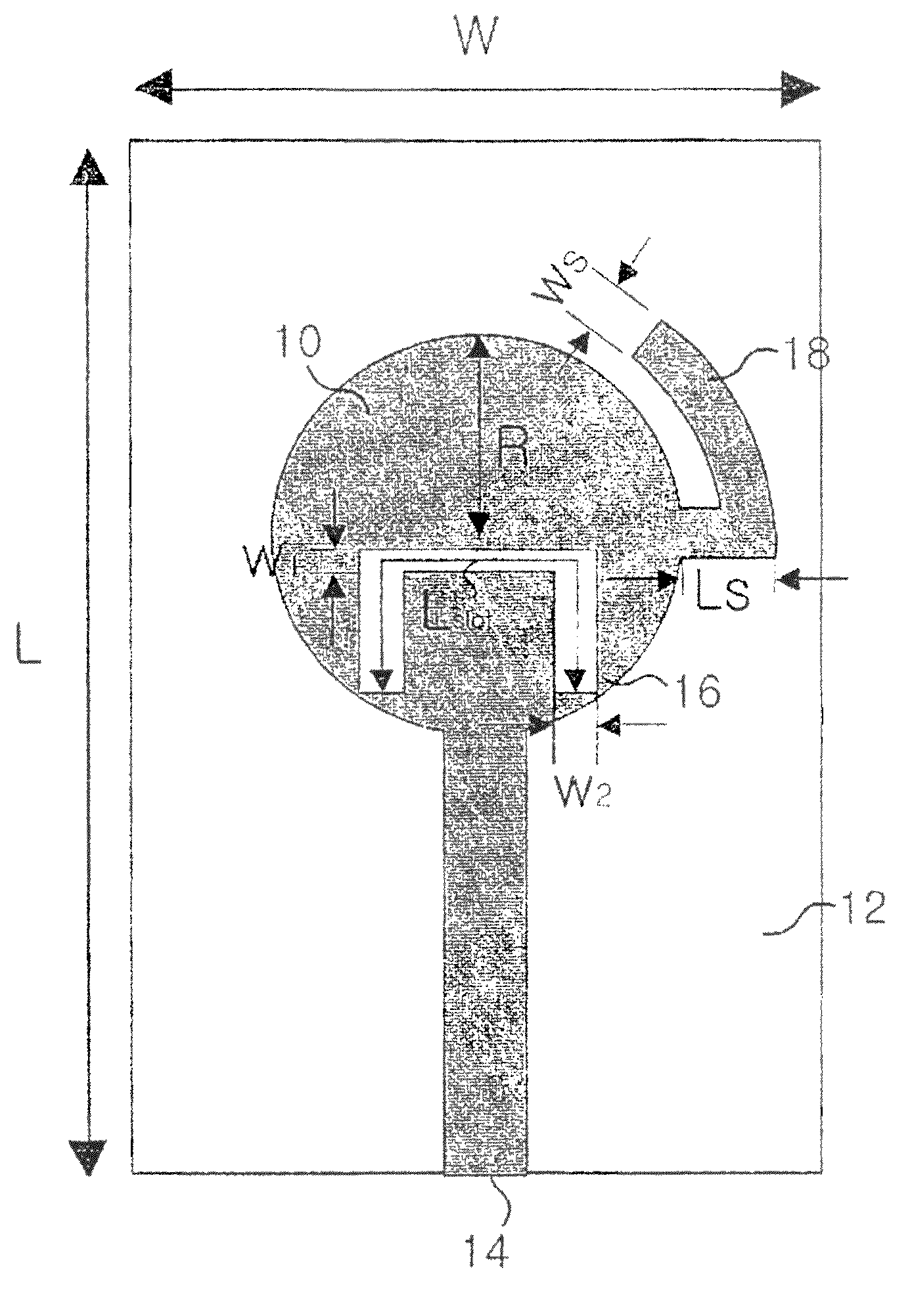
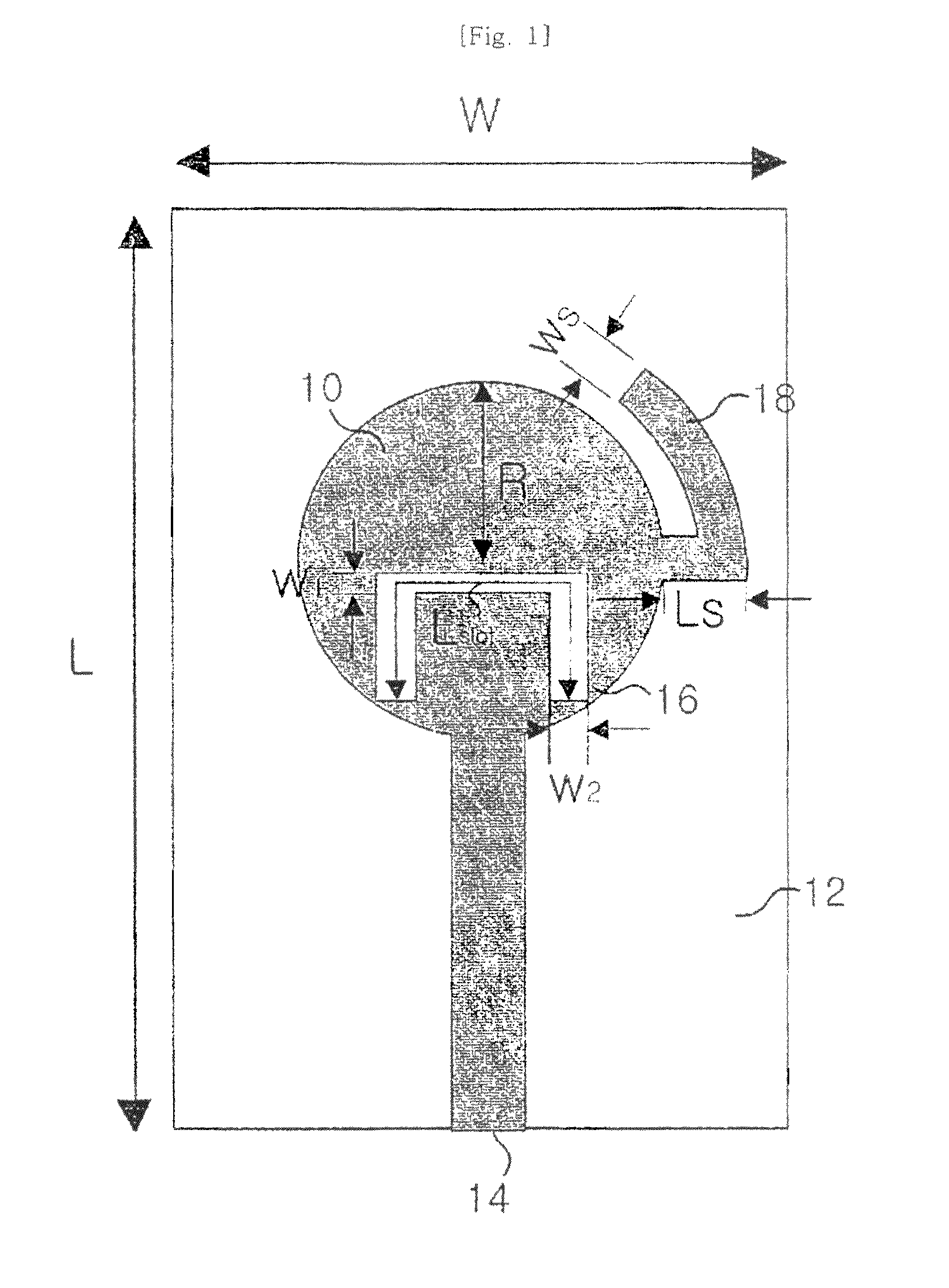
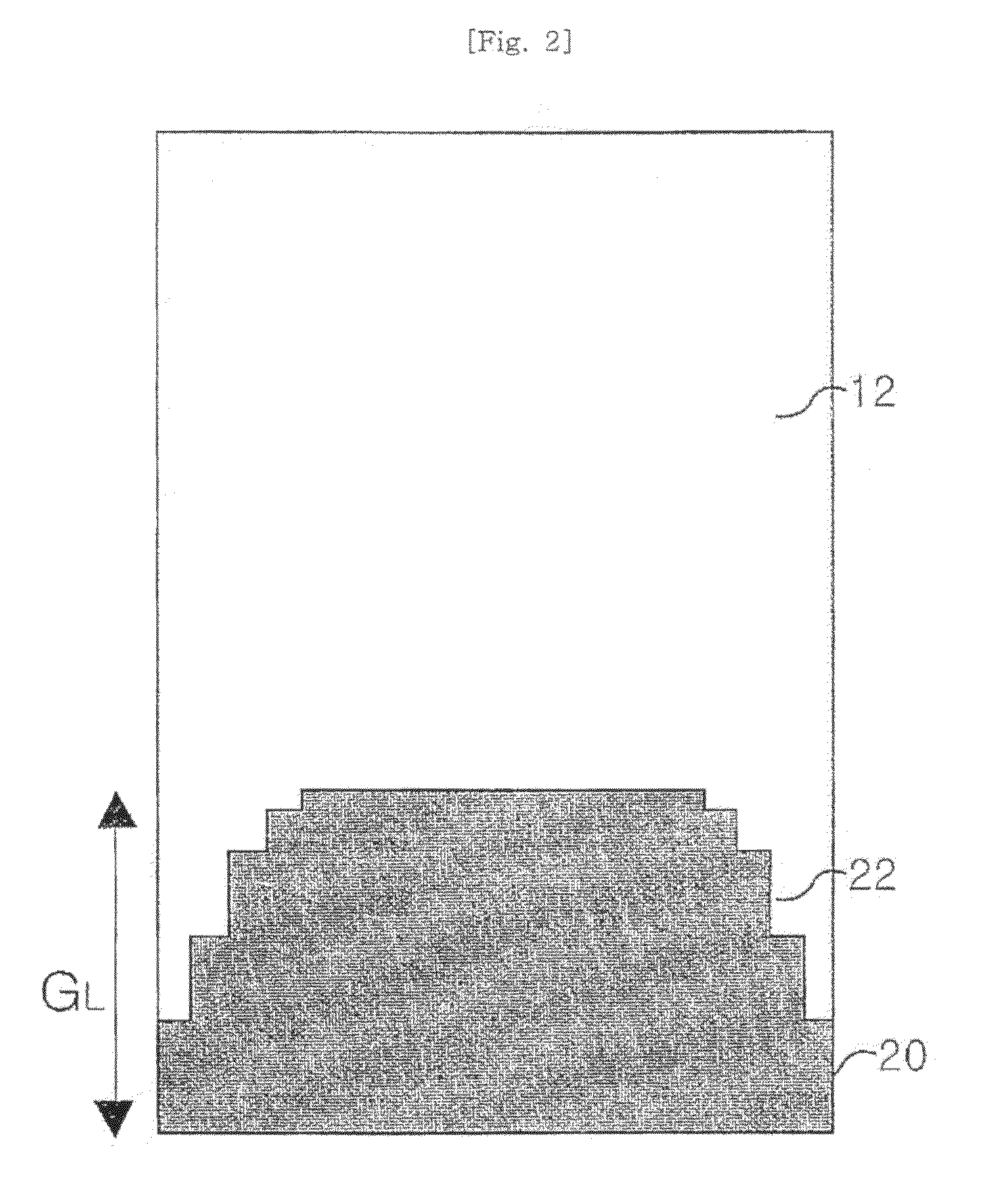
[0057]FIGS. 1 and 2 are top and bottom views of a UWB antenna according to an embodiment of the present invention.

[0058]The antenna of the present embodiment is basically a microstrip patch antenna, and it includes a substrate 12, a circular radiating element 10 formed on a top surface of the substrate, a feeding element 14 connected to the radiating element 10, and a ground plane 20 formed on a bottom surface of the substrate. An inverse U-shaped slot 16 may be formed in the radiating element 10. Steps 22 may be formed at both sides of an upper side of the ground plane 20. Furth...


PUM


Abstract

The present invention discloses an antenna for ultra-wideband (UWB) communication having a band-stop characteristic. According to an embodiment of the present invention, the UWB antenna is a patch antenna employing microstrip feeding. In order to expand a bandwidth at a low frequency band, a stub is formed in a radiating element. Furthermore, since steps are formed in a ground plane, an antenna characteristic at an intermediate frequency band can be improved and a UWB characteristic can be obtained. According to another embodiment of the present invention, the UWB antenna is a patch antenna employing microstrip feeding and has a recess formed in the ground plane, thereby implementing the UWB characteristic. The antenna of the present invention has an inverse U-shaped slot formed in the radiating element, thus implementing the band-stop characteristic at the UNII band. In addition, the antenna of the present invention has includes a ground plane having a small area and has omnidirectional radiating patterns accordingly.

Description

CROSS-REFERENCE TO OTHER APPLICATIONS[0001]This is a National Phase of International Application No. PCT / KR2006 / 001545, filed on Apr. 25, 2006, which claims priority from Korean Patent Application No. 10-2005-0034429 filed on Apr. 26, 2005 and Korean Patent Application No. 10-2005-0034430 filed on Apr. 26, 2005.TECHNICAL FIELD[0002]The present invention relates to an antenna for an Ultra-Wideband (UWB) communication system, and more particularly, to an UWB antenna having a band-stop characteristic at a frequency band of 5 GHz.BACKGROUND ART[0003]An UWB communication system is defined as a communication system having a bandwidth of 25% or more of a center frequency, or 1.5 GHz or more. UWB communication employs a signal whose power is diffused over a wide frequency band, such as an impulse signal. That is, a pulse having a several nanosecond to picosecond width (duration) is used in order to diffuse power over a wide frequency band of a GHz order. The UWB communication scheme is a co...

Claims


Application Information

Patent Timeline
Patent Type & Authority Patents(United States)
IPC IPC(8): H01Q1/38
CPCH01Q1/38H01Q9/0407H01Q9/40H01Q9/42H01Q13/10H01Q13/103
Inventor RYOU, BYUNG-HOONSUNG, WON-MOCHOI, JAE-HOONCHOI, WOO-YOUNGROH, YANG-WOON
Owner EMW CO LTD
Learn More