
Nanopatterned surfaces and related methods for selective adhesion, sensing and separation

a technology of nano-patterned surfaces and sensing, applied in chemical methods analysis, instruments, porous material analysis, etc., can solve the problems of high cost of production, high cost of surface chemistry, and labor or equipment costs, and achieve the effect of avoiding costly patterning technologies

Active Publication Date: 2012-02-21
UNIV OF MASSACHUSETTS
View PDF8 Cites 18 Cited by
  • Summary
  • Abstract
  • Description
  • Claims
  • Application Information

AI Technical Summary

Benefits of technology

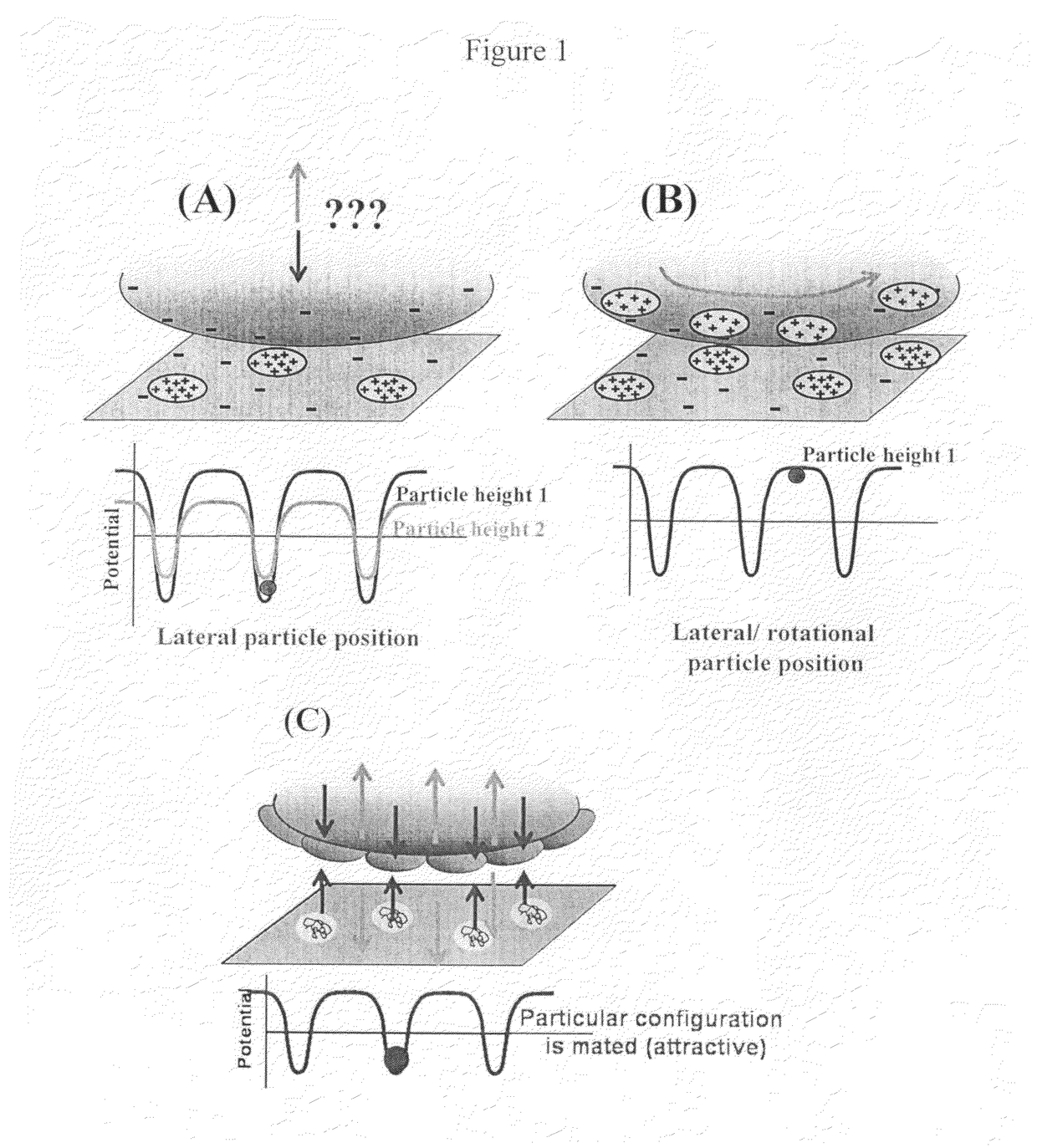
The present invention provides selective separation and sensing compositions and articles that can overcome various deficiencies and shortcomings of the prior art. The invention is based on the use of heterogeneous surfaces with spatially distributed components that interact with particles or analytes in a size range-dependent manner. The invention can provide a surface that is selective for particles or analytes of a specific size range or physical / chemical profile characteristic. The invention can also provide a method for sensing particles or analytes through a heterogeneous surface by utilizing variations in surface charge, hydrophobicity, or other physical or chemical characteristics of the surface components. The invention can also provide a method for selective interaction with particles or analytes of a specific size range or physical / chemical profile characteristic. The invention can also provide a heterogeneous surface that is robust to pH, temperature, and other environmental factors and can interact with a range of particles or analytes. The invention can also provide a method for selective separation of particles or analytes from a medium or plurality of different particles or analytes.

Problems solved by technology

Such methods are labor or equipment intensive.
Scribe-type methods (AFM-writing, e-beam lithography, with nanometric resolution) are not only both labor and equipment intensive, but are also substantially limited in terms of surface chemistry.
Only recently have interference methods been applied to e-beam lithography, but at the cost of production limited only to regular patterns.
However, such systems of the prior art tend to be limited to detection of specific sensor-analyte chemical or immunological interactions.
As a result, improved detection continues to present on-going fabrication challenges.

Method used


Image

  • Nanopatterned surfaces and related methods for selective adhesion, sensing and separation
  • Nanopatterned surfaces and related methods for selective adhesion, sensing and separation
  • Nanopatterned surfaces and related methods for selective adhesion, sensing and separation

Examples


example 1a

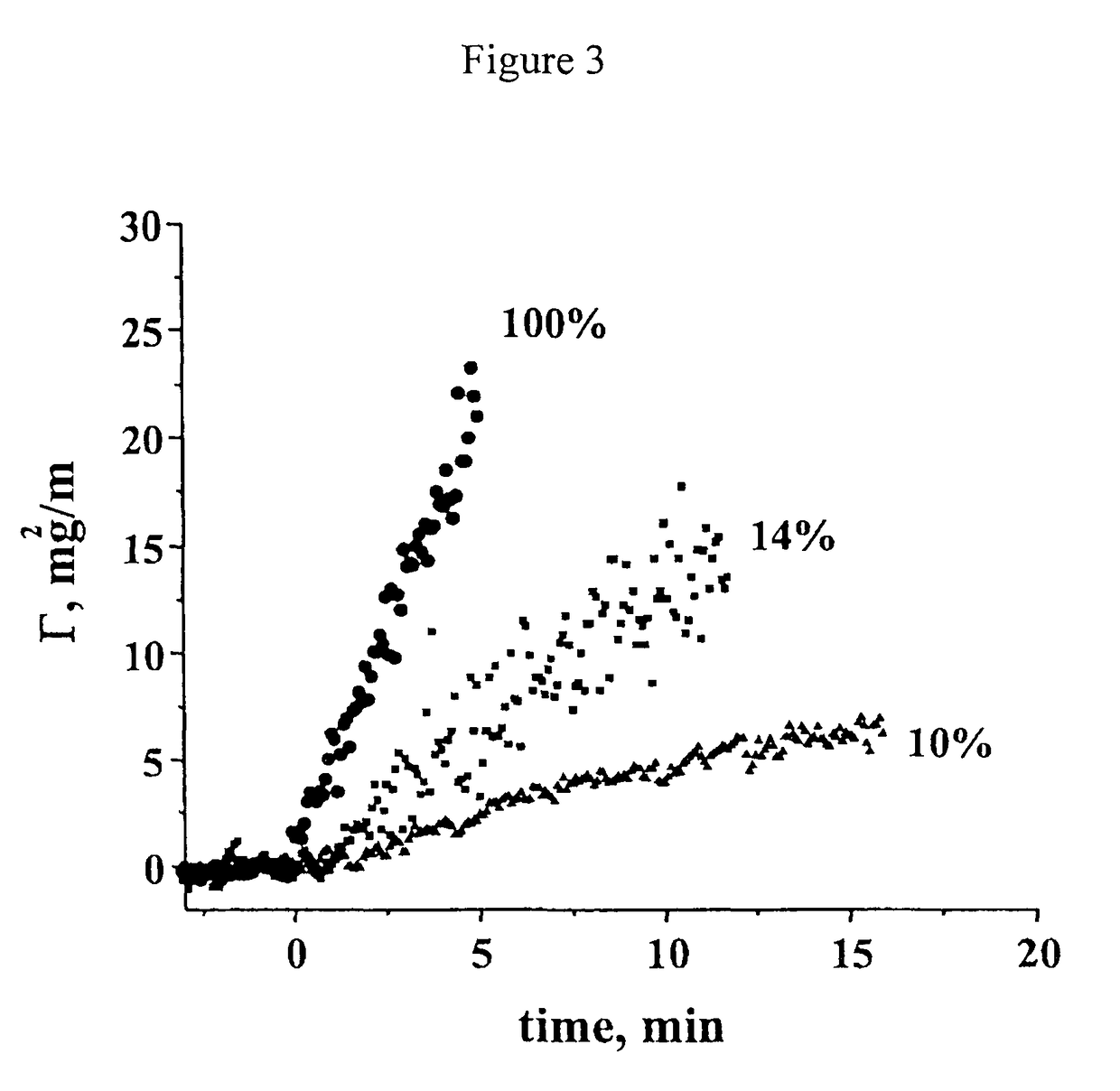
[0082]Charge-wise-heterogeneous planar surfaces were generated by adsorbing varied amounts of pDMAEMA onto these silica surfaces from a 20 ppm flowing pH 6.1 buffered solution (at ionic strength, I=0.026M), using a laminar slit flow cell with a 10×40 mm slit machined into a black Teflon block and sealed against the microscope slide substrate using an o-ring. Continuous gentle flow (with wall shear rates in the range 10-50 s−1) maintained a constant bulk solution concentration and defined the mass-transport conditions. Saturated (completely positive and overcompensating the underlying silica substrate) surfaces were generated by allowing the pDMAEMA solution to flow over the surface for a few minutes longer than needed to saturate the surface. To generate heterogeneous surfaces, adsorption from gentle shearing flow was allowed to proceed only for a few seconds (a time which was systematically varied to tune the domain density) before the flow was switched back to pure buffer. Adsorbe...

example 1b

[0083]With reference to the preceding example, various other cationic polyelectrolytes can be physically adsorbed to a negatively charged surface, silica or otherwise, to provide other heterogeneous surfaces in accordance with this invention. Likewise, such charged components can undergo further chemistry for covalent attachment to such a surface member. Alternatively, spaced components comprising one or more available anionic polyelectrolytes can be employed on a positive surface member (e.g., a cationic self-assembled monolayer) for a reversed charge configuration. While planar silica slides were used as a negative surface member / substrate, the systems and methods of this invention can be employed with other oxide surfaces or, likewise, with non-planar surface / substrate configurations, for instance, the surfaces of fibers. For instance, a positively charged surface member can be constructed from a coating or monolayer of a material such as aminopropyltriethoxysilane coupled or app...

example 2

[0084]Monodisperse silica particles serve as an analyte, to exemplify the workings of the invention. Microscopy and optical reflectometry detection methods sense all silica particles utilized, while total internal reflectance fluorescence and fluorescence microscopy require fluorescent silica particles. In the case of fluorescent particles, they were synthesized such that a fluorescent dye resides in the core of the particle. The outer shell of the silica particle contains no dye and presents a pure silica surface (with negative charge) to the surrounding fluid. The fluorescent cores of some samples of particles allowed them to be distinguished from other, non-fluorescent particles that were added to the analyte suspension in some of the examples below.

[0085]To synthesize colloidal silica particles with fluorescent cores, a modified Stober process was used. (See, Vanblaaderen, A.; Vrij, A. Langmuir 1992, 8, 2921-2931; Stober, W.; Fink, A.; Bohn, E. Journal of Colloid and Interface S...


PUM

PropertyMeasurementUnit
distanceaaaaaaaaaa
sizeaaaaaaaaaa
sizeaaaaaaaaaa

Abstract

The invention is comprised, in part, of a surface that contains more than one component or construct. Such heterogenous surface compositions and configurations, related systems and methods for sensing particle or analyte interaction therewith can selectively and / or differentially interact with a range of particles / analytes, in lieu of specific molecular sensor-analyte interactions for each particle. These interactions of various analytes or particles can differ sufficiently in strength and range between multiple analyte types or particles to effect a separation of analytes or particles mixtures, in a way that requires no sensing or detection. With incorporation of a sensing mechanism, discrimination / detection of different compounds within an analyte mixture can be accomplished.

Description

[0001]This application is a continuation-in-part of and claims priority benefit from prior application Ser. No. 11 / 592,454 filed Nov. 3, 2006 now U.S. Pat. No. 7,752,931 and provisional application Ser. No. 60 / 732,941 filed Nov. 3, 2005, and from prior provisional application Ser. No. 60 / 936,861, filed Jun. 22, 2007—each of which is incorporated herein by reference in its entirety.[0002]The United States government has certain rights to this invention pursuant to Grant Nos. CTS-0234166 and CTS-0242647 from the National Science Foundation to the University of Massachusetts.BACKGROUND OF THE INVENTION[0003]Nanometric surface design has been a research focus over the past decade, with a variety of concepts and methods developed. Most produce features with a size scale greater than 100 nm (e.g., standard photolithography, microcontact printing and / or with regularity interference methods). Such methods are labor or equipment intensive. Consider, for instance, the fabrication of a lithogr...

Claims


Application Information

Patent Timeline
Patent Type & Authority Patents(United States)
IPC IPC(8): G01N15/00G01N27/60G01N15/10C12Q1/00B82Y15/00
CPCB82Y30/00G01N33/54306G01N33/54346G01N33/54366G01N33/54393G01N33/552Y10S977/953Y10S977/957
Inventor SANTORE, MARIA MONICAKALASIN, SURACHATE
Owner UNIV OF MASSACHUSETTS
Learn More