System for stabilizing gas hydrates at low pressures

a gas hydrate and low pressure technology, applied in the direction of liquid chemical processes, gas-gas reaction processes, liquid-gas reactions of thin-film type, etc., can solve the problems of high capital costs of liquefied natural gas plants to justify the cost, etc., to achieve low capital costs, economic viability and safety, and minimize decomposition

Inactive Publication Date: 2012-02-21
MISSISSIPPI STATE UNIVERSITY
View PDF4 Cites 3 Cited by
  • Summary
  • Abstract
  • Description
  • Claims
  • Application Information

AI Technical Summary

Benefits of technology

[0013]This invention provides a practical, economically viable, and safe means for stabilizing gases in sI and sII hydrate forms. One object of the invention is to provide a means for stabilizing gases (and also minimizing the decomposition), such as natural gas and its components, in a gas hydrate form so that the gases can be stored and transported at pressures and temperatures that are considered safe by industry standards. In accordance with the present invention as described herein, a method and system for storing gases is provided that comprises forming and stabilizing gas hydrates in the presence of a water-surfactant solution.
[0014]Some advantages of this new process, system, and / or apparatus include, but are not limited to, the following: (1) liquefied natural gas can be expensive and liquefied natural gas plants typically have high capital costs and must be built at large gas fields to justify the cost. The system of the present invention to store natural gas at 1 atm may service smaller gas fields economically; (2) storage conditions for the storage system and process disclosed herein are less stringent than liquefied natural gas from the standpoint of temperature and pressure storage; (3) liquefied natural gas storage near populated areas or docking facilities may raise serious safety concerns and potential fire and explosion risks. The gas hydrate system of the present invention is safe since, in a simplistic view, the gas is encased in ice. Gas from gas hydrate is released only after transfer of heat to decompose the solid water host structure. In an era of terrorist threats, this safety issue becomes critical; (4) other gas hydrate processes that may be stable at 1 atm have little if any potential to be economical on a large scale. Other ultrastable gas hydrate processes involve the slow conversion of ice to hydrates. The system and process of the present invention provides a rapid means to generate stable hydrates; (5) the system and process of the present invention provides a product that is stable upon the initial release of pressure after forming the hydrates. State-of-the-art processes have perhaps a 50% or so decomposition and release of their stored gases. Although their remaining gases may be stably sequestered, the 50% or so decomposition loss cannot be tolerated for any viable commercial use due to the economics of such loss; and (6) the system and process of the present invention is economical and fast and has the potential of being utilized for storing gases economically on a large scale.

Problems solved by technology

Some advantages of this new process, system, and / or apparatus include, but are not limited to, the following: (1) liquefied natural gas can be expensive and liquefied natural gas plants typically have high capital costs and must be built at large gas fields to justify the cost.
In an era of terrorist threats, this safety issue becomes critical; (4) other gas hydrate processes that may be stable at 1 atm have little if any potential to be economical on a large scale.

Method used


Image

  • System for stabilizing gas hydrates at low pressures
  • System for stabilizing gas hydrates at low pressures
  • System for stabilizing gas hydrates at low pressures

Examples


example 1

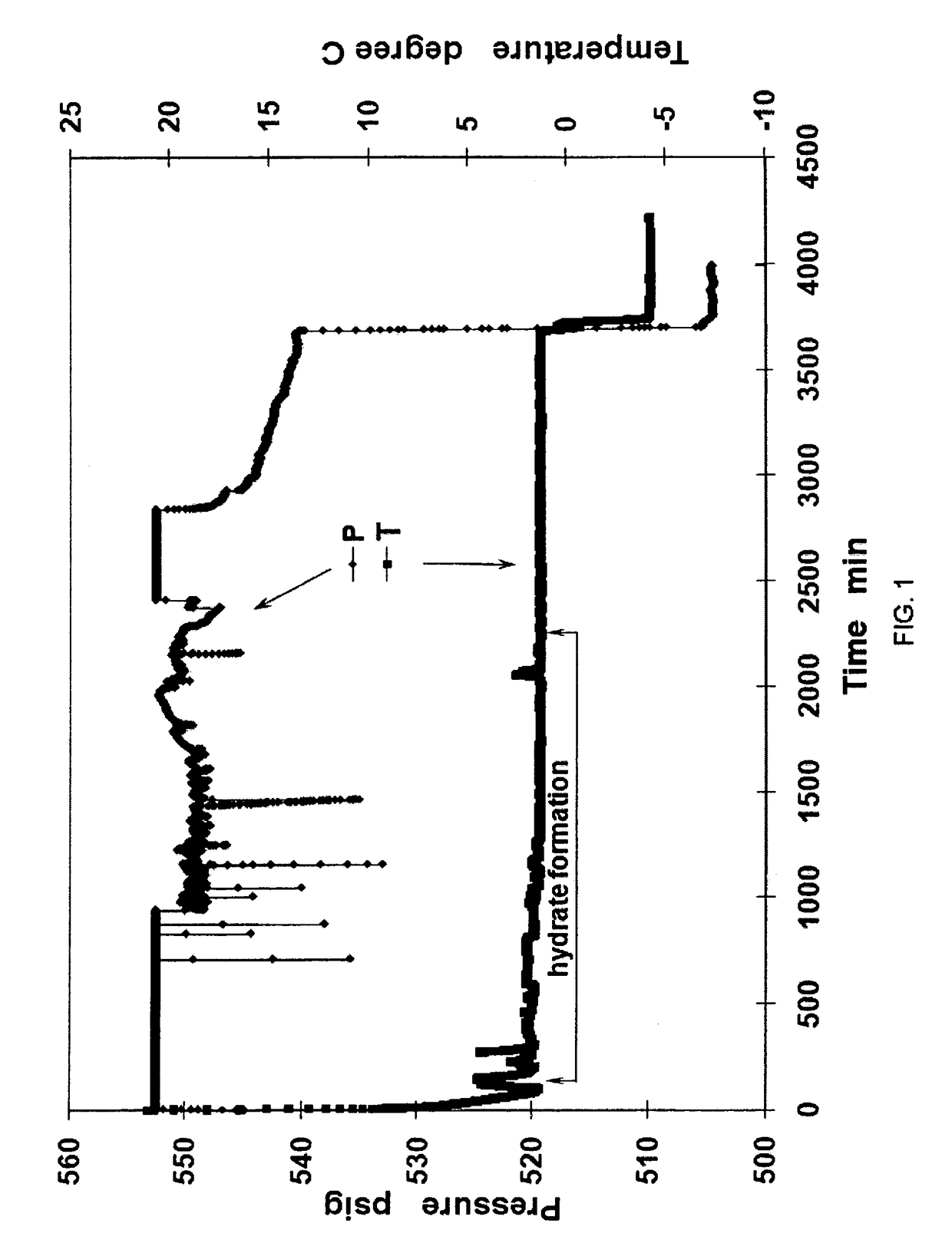
[0032]In preparation of methane hydrates, a 1-inch diameter aluminum (Al) pipe of 5.5 inch length (1 inch diameter) was placed in the center of the 500 mL test cell. Methane hydrates were generated from 300 ml of 300 PPM sodium dodecyl sulfate (SDS) distilled water solution at +0.5° C. and under constant pressure of 3.84 MPa methane. After hydrate formation, methane hydrates were cooled down to −5.0° C. Upon depressurization to one atm in 5 seconds, methane hydrates exhibited great stability below −1.0° C. both during and after depressurization. The evolutions of pressure and temperature during hydrate formation are shown in FIG. 1. FIG. 4 is a table showing data values from the Example 1 process.

[0033]FIG. 1 defines the pressure-temperature-time parameters for the formation of methane gas-hydrates that exhibit ultra-stability when pressure is lowered to 1 atm for storage or transportation. The pressure (P) and temperature (T) traces as a function of time reflect the step sequences ...

example 2

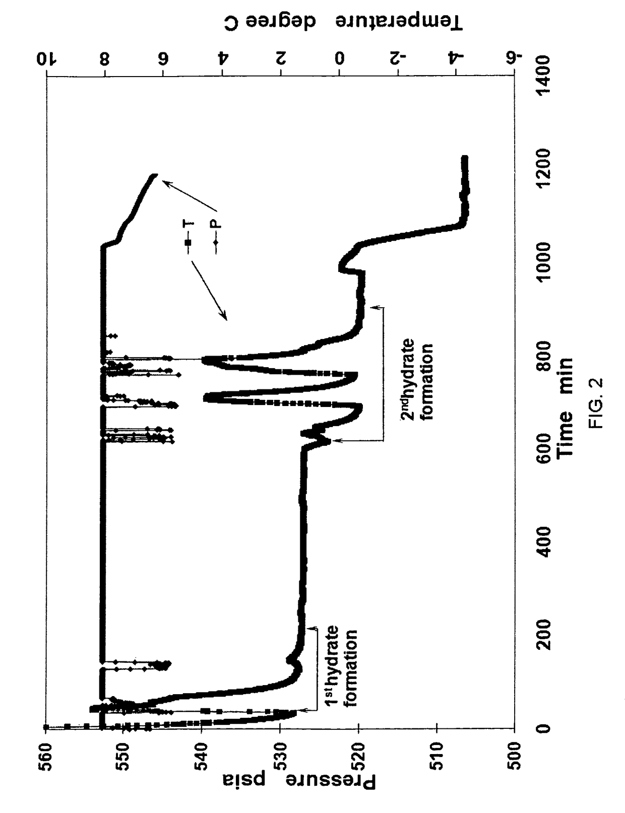
[0044]During the formation of natural gas hydrates, a 1-inch diameter copper (Cu) pipe or solid Cu cylinder of 5.5 inches length was placed in the center of the 500 mL test cell. Natural gas hydrates were created in two steps. In the first step, 250 ml of SDS distilled water solution was added to the test cell and hydrates were produced at +0.5° C. under constant pressure of 3.84 MPa natural gas consisting of 90% methane, 6% ethane, and 4% propane. In the second step, when cooled to −1.5° C. at the same constant pressure of 3.84 MPa, natural gas hydrates grew again from the remaining free water. Thereafter, when hydrate formation was completed in the second step, hydrates were cooled down to −5.0° C. Upon depressurization to one atmosphere in 5 seconds, natural gas hydrates exhibited great stability below −1.0° C. both during and after depressurization. Variation of pressure and temperature during hydrate formation is given in FIG. 2. FIG. 5 is a table showing data values from the E...

example 3

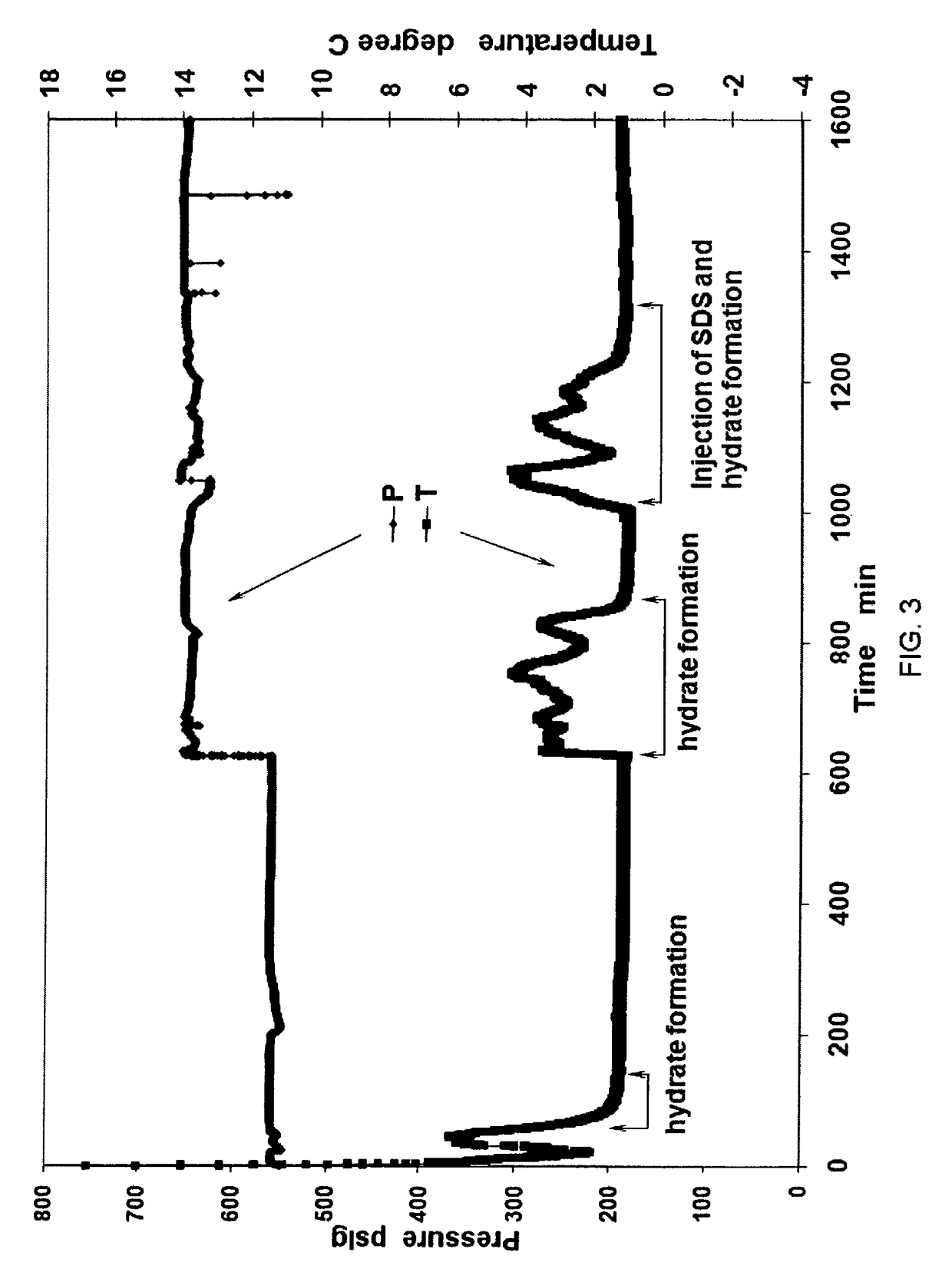
[0057]During the formation of natural gas hydrates, a 1-inch diameter Cu pipe of 5.5 inches length was placed in the center of the 500 mL test cell. Next, 250 ml of SDS solution was added to the test cell. At first, natural gas hydrates were created under a constant temperature of +0.5° C. and a constant pressure of 3.84 MPa. Then, secondly the pressure inside the test cell was increased to 4.53 MPa to react the remaining free water into hydrates. When hydrate formation was finished, an SDS solution of up to 100 ml was injected into the test cell to form gas hydrates again at +0.5° C. and 4.53 MPa. After additional hydrate formation, methane hydrates were cooled down to −5.0° C. Upon depressurization to one atm in 5 seconds, natural gas hydrates demonstrated great stability below −1.0° C. FIG. 3 shows the record of pressure and temperature during hydrate formation. FIG. 6 is a table showing data values from the Example 3 process.

[0058]FIG. 3 defines the pressure-temperature-time par...


PUM

PropertyMeasurementUnit
temperatureaaaaaaaaaa
pressureaaaaaaaaaa
pressureaaaaaaaaaa

Abstract

The present invention provides a system for stabilizing gas and particularly gas hydrates at low pressures and for safe storage and transportation of the gas. The invention also provides minimization of the decomposition of the gas in hydrate form.

Description

CROSS-REFERENCE TO RELATED APPLICATION[0001]This application claims priority from U.S. Provisional Patent Application Ser. No. 60 / 994,087 filed Sep. 17, 2007. The entirety of that provisional application is incorporated herein by reference.FIELD OF THE INVENTION[0002]The present invention relates to a system for stabilizing gas, more specifically, for stabilizing gas in a hydrate form at pressures safe for storing and transporting said gas while minimizing the decomposition of the hydrate form.BACKGROUND OF THE INVENTIONDescription of Prior Art[0003]Natural gas can be stored by various means including compressed gas storage, liquified gas storage, underground storage, and adsorption. Types of such natural gas or any of its components include gas compositions composed primarily of methane but may also contain other components such as ethane, propane, isobutane, butane, CO2, and / or nitrogen. However, current gas storage means have potential problems and deficiencies, namely that liqui...

Claims


Application Information

Patent Timeline
Patent Type & Authority Patents(United States)
IPC IPC(8): B01J3/00B01J19/00C07C9/00
CPCF17C11/007
Inventor ROGERS, RUDY E.ZHANG, GUOCHANG
Owner MISSISSIPPI STATE UNIVERSITY
Why Eureka
Try Eureka