
Multiphase reactor

a multi-phase reactor and reactor technology, applied in the direction of dispersed particle separation, chemical/physical/physico-chemical processes, separation processes, etc., can solve the problem that the rotation surface cannot fit into complicated practical situations, and achieve the effect of simple structure and enhanced reaction strength

Active Publication Date: 2012-02-21
SHI HANXIANG
View PDF8 Cites 10 Cited by
  • Summary
  • Abstract
  • Description
  • Claims
  • Application Information

AI Technical Summary

Benefits of technology

"The present invention is a multiphase reactor with a simple structure and enhanced reaction strength. It is designed to have a rotary build-in member with a conical surface and an annular axisymmetric body, which are formed by rotating curved lines around a rotation axis. The reactor has a cylindrical shell with a smooth inner surface. The reactor can have one or more reaction units, with each unit consisting of the shell, the axisymmetric body, and the annular axisymmetric body. The reactor has improved reaction process control and enhanced contact of gas-liquid-solid three-phase through the design of the rotary surface and the formation of fluid curtains with different diameters. The structure of the reactor is simple and easy to manufacture, assemble, and install."

Problems solved by technology

However, these rotation surfaces can hardly fit for complicated practical situations.

Method used


Image

  • Multiphase reactor
  • Multiphase reactor
  • Multiphase reactor

Examples


example 1

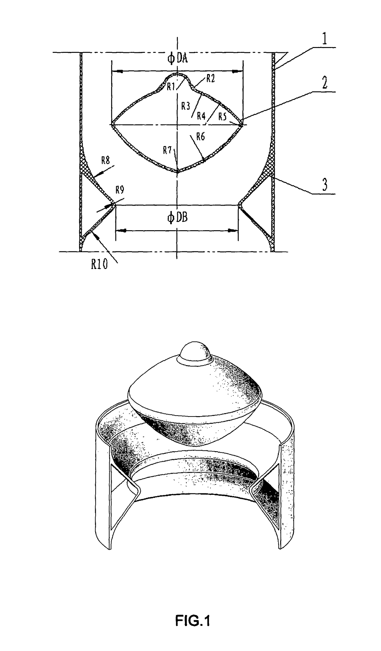
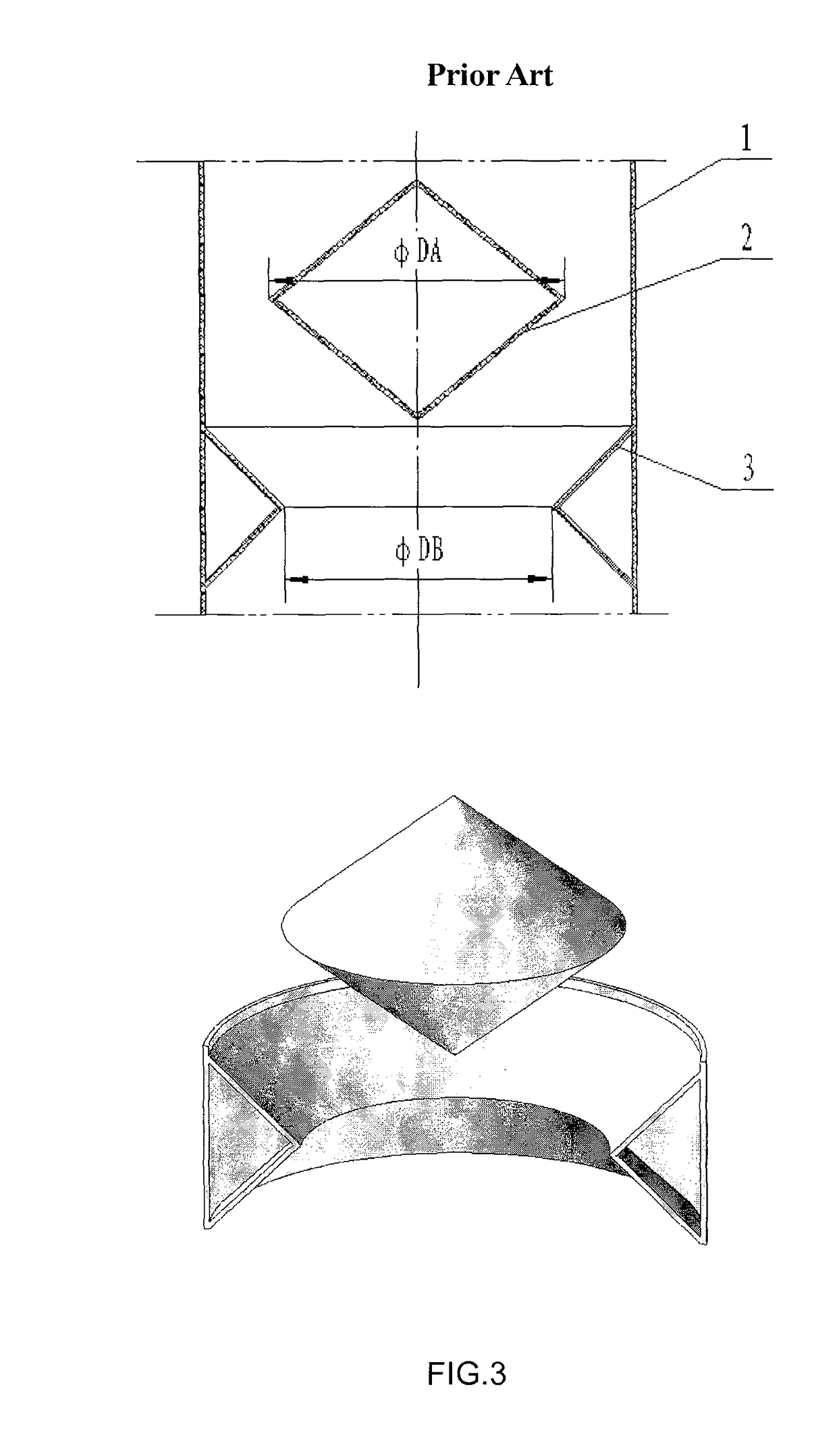
[0017]As shown in FIG. 1, the multiphase reactor includes a shell and a rotary build-in member. The shell 1 of the reactor can be made as a cylinder with smooth surface. The rotary build-in member, consisted of the axisymmetric body 2 and the annular axisymmetric body 3, is installed inside the shell 1. The axisymmetric body 2 is formed by rotating the curved line which is formed by connecting several arcs with different radii. It is obviously different from the cone in FIG. 3. The annular axisymmetric body is also formed by rotating the curved line, which is formed by connecting several arcs with different radii, and is different from the conical ring in FIG. 3. The annular axisymmetric body 3 can be welded or riveted on the shell 1 of the reactor, and the axisymmetric body 2 is supported on the shell 1 by a fixed bolster. The axisymmetric body is mounted on the annular axisymmetric body with enough space left in between, whereby the fluids can flow through smoothly. The diameter o...

example 2

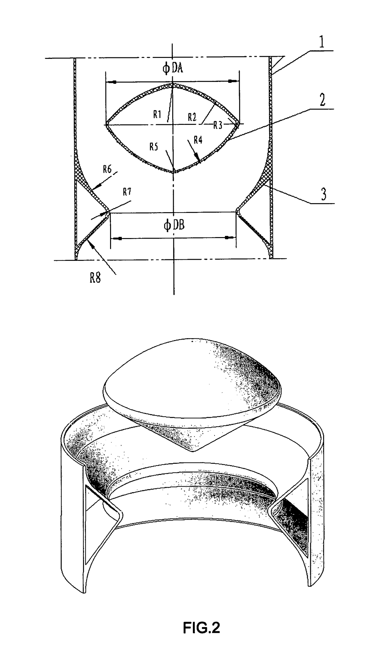
[0018]As shown in FIG. 2, the multiphase reactor includes a shell and a rotary build-in member. The shell 1 of the reactor can be manufactured into a cylinder shape, the rotary build-in member, composed of the axisymmetric body 2 and the annular axisymmetric body 3, is installed inside the shell 1. The axisymmetric body 2, formed by rotating another curved line, has the shape that is different from the cone body shown in FIG. 3 and the axisymmetric body shown in FIG. 1. The annular axisymmetric body 3, formed by rotating another curved line, has the shape that is different from the conical ring shown in FIG. 3 and the annular axisymmetric body shown in FIG. 1. The axisymmetric body is mounted on the annular axisymmetric body with enough space left in between, whereby the fluids can flow through smoothly. The diameter φDA of the axisymmetric body 2 is not less than the inner diameter φDB of the annular axisymmetric body, so as to strengthen the change of the fluid velocity and to spe...


PUM


Abstract

This invention relates to a multiphase reactor which is especially suitable for desulfurization of flue gas. A rotary build-in member comprising a axisymmetric body and an annular axisymmetric body is fixed on the shell of the reactor. The shell is cylindrical, and its surface is smooth or waved. The maximum diameter of the axisymmetric body is no less than the inner diameter of the annular axisymmetric body. The axisymmetric body is installed on the annular axisymmetric body coaxially. One rotary build-in member and its corresponding shell constitute an unit, and the reactor may have one or more such units. The multiphase reactor can effectively improve the flow pattern of the fluid and the contact of gas-liquid-solid three-phase of the reactants, speed up the mass transfer, and prevent deposition of the solid phase. The reactor is simple in structure and convenient for use. It can be used in the fields such as environmental protection, chemical engineering, metallurgy, and architectural industries.

Description

FIELD OF THE INVENTION[0001]This invention relates to a multiphase reactor, particularly, to a gas-liquid-solid or gas-liquid, gas-solid, liquid-solid multiphase reactor.BACKGROUND OF THE INVENTION[0002]Multiphase reactors are widely used in various industry sectors such as metallurgy, chemical engineering, petrochemical engineering, and environmental protection. Owing to the particularity of different application fields, the reactor components that speed up reactions among gas-liquid-solid three-phase or gas-liquid, gas-solid, liquid-solid two-phase should have their own characteristics, according to practical requirements. For instance, the Chinese patent No. ZL98113470.x, entitled “A Multiphase Jet Osmotic Dissolution reactor”, discloses a reactor including a spherical perforated focused injector, a draft tube, an expanding vessel and an osmotic cavity. Its characteristics are that the small conical orifices on the surface of the spherical body of the spherical perforated focused...

Claims


Application Information

Patent Timeline
Patent Type & Authority Patents(United States)
IPC IPC(8): B01J8/00B01J19/32B01J19/00B01D53/18B01D53/50B01D53/80B01J8/12B01J19/18
CPCB01D53/504B01J8/12B01J19/18
Inventor SHI, HANXIANG
Owner SHI HANXIANG
Learn More